Facebook
 Google
 GitHub
 Linkedin
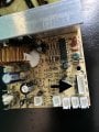
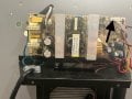
Greeting all. New to the site. Looking for some suggestions/help on trying to replace a thremoelectric wine cooler PCB. This board is from Cuisinart cwc3200, wine cooler, which is no longer in production and parts can not be found. The board was working for awhile, but is not dead. I'm trying to find a replacement which comes close to all the connections from the old board (model # PCB160531F3). I can not find anything close, specifically the black arrow to a 5 pin connection for PWM, NTC and +12v. The wine cooler has 4 fans, 2 internal and 2 external (Peltier system). Besides the 5 pin connection, it has 6 other connections. From all of my searches to find a close replacement, the biggest issue is trying to replace the 5 pin connector.
The other 6 connections I might be able to come close to on a replacement board. The old board also has 4 grd spade connections, I can find a board that has 2 spade grounds, but not 4. Assuming i can not find a 5 pin replacement on a new board, is my only option to somehow separate/rewire the 5 pin connections to individual connections on the new board. I'm assuming the new board may/should have separate PWM and NTC connections.
I'm open to any ideas to get this cooler to work. It's so old that it may require rewiring and searching for a new board that will fit everything i need with 4 Peltier system. Of course, it may not be worth fixing because of the cost to get it up and running vs buying a new one.
The cooler has a temp LED display and two LED controls to raise and lower the temp and an internal light (which i don't need).
Thanks to all for any suggestions you have, including putting it in the dump")
The other 6 connections I might be able to come close to on a replacement board. The old board also has 4 grd spade connections, I can find a board that has 2 spade grounds, but not 4. Assuming i can not find a 5 pin replacement on a new board, is my only option to somehow separate/rewire the 5 pin connections to individual connections on the new board. I'm assuming the new board may/should have separate PWM and NTC connections.
I'm open to any ideas to get this cooler to work. It's so old that it may require rewiring and searching for a new board that will fit everything i need with 4 Peltier system. Of course, it may not be worth fixing because of the cost to get it up and running vs buying a new one.
The cooler has a temp LED display and two LED controls to raise and lower the temp and an internal light (which i don't need).
Thanks to all for any suggestions you have, including putting it in the dump
Attachments
-
 2.3 MB Views: 40