Thermocouple amplification - noise suppression

Thread Starter

g.b

Joined Dec 20, 2017
7
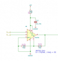
I have the attached circuit used as an amplifier for a K type thermocouple, I get a 50Hz noise - the noise appears on both thermocouple inputs and gets amplified - thermocouple wires are shielded with the shield connected to chassis (which is earthed).

Trying to understand the problem I saw that the noise actually comes from the GNDREF node (which is the 0V of the power supply). Connected a 0.1uF capacitor between GNDREF and the chassis and this solved the problem.

I wonder if there is another way to suppress this noise.
Note: later on the circuit will get power from an isolated DC-DC converter, but at the moment it is connected to a lab power supply, so maybe when the isolated supply will be ready the problem will not appear, however I would like to know if there can be another solution at the current stage.
 

Attachments

Audioguru again

Joined Oct 21, 2019
6,691
Many electret microphones produce a very low level signal and are placed away from the electronics. They do not need an expensive instrumentation amplifier with balanced inputs, instead they use a single wire that has a shield connected to the 0V of the circuit and an inexpensive audio opamp. They produce no hum nor any other interference.
 

KeithWalker

Joined Jul 10, 2017
3,091
As IanO pointed out, there is no common mode reference in your circuit. See "Input bias current return" in the datasheet:

"For proper operation, a path must be provided for input bias currents for both inputs. Without input bias current paths, the
inputs will float to a potential that exceeds common-mode range and the input amplifier will saturate."
 

Thread Starter

g.b

Joined Dec 20, 2017
7
You make no mention beyond Type K of your choice of thermocouple? Sheath? If a sheath is it grounded or ungrounded? Also the INA 332 does not offer CJC (Cold Junction Compensation) so is not really a good choice as drawn. There are better chips designed around working with thermocouples. I suggest you read the links. Also Google type k thermocouple amplifier with cold junction compensation for better amplifier suggestions.

Ron
I do not really measure temperature - the thermocouple is for flame sensing so the readings between no flame" and "flame" are far apart
 

Thread Starter

g.b

Joined Dec 20, 2017
7
As IanO pointed out, there is no common mode reference in your circuit. See "Input bias current return" in the datasheet:

"For proper operation, a path must be provided for input bias currents for both inputs. Without input bias current paths, the
inputs will float to a potential that exceeds common-mode range and the input amplifier will saturate."
Thanks - this may be the problem. Will try it
 

Reloadron

Joined Jan 15, 2015
7,517
I do not really measure temperature - the thermocouple is for flame sensing so the readings between no flame" and "flame" are far apart
Not caring about actual temperature and only flame sensing as in flame or no flame I would use a flame sensing rod or UV flame sensor. However a thermocouple will work just fine as used in early furnace applications to sense a pilot light flame. In for example a commercial boiler or furnace I would run with a commercial flame sensor but again a thermocouple will do.
As suggested look at grounding.


Ron
 
Top