i want speed controller, not just turn on/off
In the logic level MOSFET, MCU pin is overloaded
I'm going to use PC817, but it's only on/off
I am looking for suitable Vgs using the Voltage Divider for 24
However, I don't know the R value at which Mosfet turns on/off quickly.
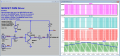
You are still barking up the wrong tree. This is how you do PWM. The purpose of the sawtooth Ramp is to sample the value of Ref using a comparator to change the value of pwm when (Ramp - Ref) changes sign. In normal operation Ref would some reference voltage that you would use to control the pulse width. I made it a lower frequency triangle wave to demonstrate the change in duty cycle.
1. What I was going to do
- DC Motor PWM speed control (24V/2.3A)
- If i run LOGIC LEVEL MOSFET directly with MCU's I/O pin,
the MCU will be overloaded
2. Components Used
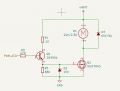
- LR7843, PC817. 2N3904
3. Important part of a circuit
- Lower the input voltage(24v) to the appropriate voltage(10~12v)
for the MOSFET gate
4. A mistake
- Think optocoupler is faster than bjt(Misunderstanding of optocoupler)
- Current limit resistance member of zener diode
- Calculation error of voltage divider(After the voltage divider is used as the resistance,
the Zener diode may be used as Mosfet's gate protection. Not for voltage limitation.)
- The biggest mistake is working on the breadboard(it makes heat problem too)
5. The last circuit
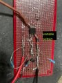
no heat works fine.
It's definitely calculated right, but it's not working because of the problem with the breadboard, so it's very confusing
(especially the Voltage Divider)
I thought it was a simple circuit rather than using the Motor Driver IC
The MOTOR doesn't need a lot of current however, I am thinking of using Motor driveric for safety.
I reread the post from the beginning. I think I'm a troll.
Once again, I'm sorry to everyone who answered. And thank you.
sorry for that i tried all the circuits all night. I didn't have many parts, so I bought the rest late.
As mentioned above, it was blocked in one part for a long time due to breadboard problems.
but the voltage on the base won’t be 0.65V, because you have an emitter follower: R3 is superfluous.
and why do you want to limit the current into the MOSFET gate? You don't want to slow it down.
but the voltage on the base won’t be 0.65V, because you have an emitter follower: R3 is superfluous.
and why do you want to limit the current into the MOSFET gate? You don't want to slow it down.
NO!! Limiting the output (controlled variable) in a feedback system will usually reduce any stability by adding non-linear response.
NEXT: the basic concept of a PWM system is to switch the applied power between zero and some maximum value, and have the inertial averaging of the controlled device do the smoothing back into an intermediate value. but from the initial post forward it has not been aiming in that direction. The mosfet transistor should have been switching between cutoff and saturation, unfortunately the response times were not in line with the frequency selected, it seems.
The gate drive signal was not enough to put the transistor into saturation, and all of the capacitors assured that there would be no rapid changing of the voltage applied to the motor. In a linear analog system that could be fine, but the claim was to be wanting PWM control of the motor..
PWM control is indeed switching on and off completely and quickly. The motor inertia is what delivers the averaged power through varied torque and speed.
It's just that I'm lucky that the frequency isn't high, so it's not loaded
So the circuit that I made was something that looked normal
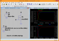
Thank you. I'll check it properly with the oscilloscope.
(I programmed the MCU to start the motor slowly and stop slowly)
It wasn't just programming that delayed the discharge time
I'm sorry to see this late.
I'll refer to it in my circuit Thank you!
Now we have changed the diode a little larger capacity and added gate resistance 22R
and removed R4(1K)
It works very well the way i wanted it to

 Facebook
 Google
 GitHub
 Linkedin