They are called “logic level” MOSFETs because they can be driven from the same supply as the logic, not because they can be driven by a microprocessor pin, or the output from a logic gate.
Generally, they have twice as much gate capacitance as a standard MOSFET, so are more likely to need a high-current gate driver.
If you have a load that only switches occasionally, then switching speed is less important, and it could be switched using the limited output current from a logic gate, Or microprocessor pin.
Your MOSFET has a gate to drain capacitance of almost 1nF - personally, I wouldn’t like to have a microprocessor pin that is directly coupled to the load with 1nF. I’d put some sort of buffer between the two, either something like a 74HC125 or a proper gate driver such as MCP1402: gate drivers are rather cheaper than they used to be, and logic gates seem to have got more expensive.
Because of the very small mass of the active portion of a transistor of any kind, the power dissipated during the linear portion of the transition between cutoff and saturation will cause a fair amount of heating. so in many applications switching speed matters a lot. That is one benefit of our much faster devices. BUT it still matters.
Simulations are usually a bit different from reality. In many simulators components do not fail because of excess current, so one amp thru a quarter watt 100 ohm resistor is not an issue, as one example.
I think I know.
The heat generation of the MOSFET is greatly affected by the switching speed.
When the MOSFET, which had a severe fever at 20Khz, had a low fever at 10Khz.
To supply the appropriate power to the gate, I should aim for fast discharge according to my frequency.
What did you expect? In order to do PWM you actually have to come up with a circuit that does that. So far you have shown us nothing of the kind. I suggest that you find or design a circuit that does PWM and come back when you have something
What did you expect? In order to do PWM you actually have to come up with a circuit that does that. So far you have shown us nothing of the kind. I suggest that you find or design a circuit that does PWM and come back when you have something
i want speed controller, not just turn on/off
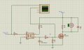
In the logic level MOSFET, MCU pin is overloaded
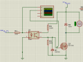
I'm going to use PC817, but it's only on/off
I am looking for suitable Vgs using the Voltage Divider for 24
However, I don't know the R value at which Mosfet turns on/off quickly.
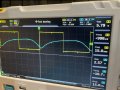
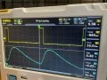
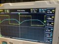
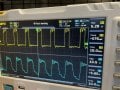
Lower the frequency to 10Khz, making noise at low Duty but working fine.
But it's a completely different result from what I calculated.
By voltage divider
R4 is 4.7K
R3 is 2.2K
Shouldn't this work as well?
[Edit:
Voltage divider -> just on/off
Zener -> PWM
is this right?]
[Edit]
when i use Voltage Divider (pair of 2.2k or 4.7k) MOSFET gets more heat
The datasheet says that Mosfet is heated by 25+3 degrees for 2A, but it's actually 38 degrees
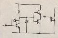
If you are absolutely determined to make a circuit That uses lots of discrete components and isn’t really all that good, the add a Baker clamp and a complementary emitter follower. It’s the circuit I used before replacing it by a gate driver IC which immediately solved all the reliability issues.
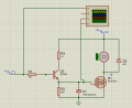
What is the required gate to source voltage to bring the FET into complete saturation? It looks to me like the drive circuit is set up to keep it in the linear region where the dissipation will be quite high.
The basic concept of a PWM drive circuit is that the power is either completely off or completely on. Is that even possible with the gate drive circuit as shown??
And what PWM effectively varies is the power, because the voltage is always the same when it is on.

 Facebook
 Google
 GitHub
 Linkedin