The JBL L75ms Repair

Thread Starter

R!f@@

Joined Apr 2, 2009
10,007
I tried to check the PSU without PFC.
The stby works, so jumped the ON terminal with 10K.

Nothing :confused:
I should have checked the IC. Found a short on it's supply.
Removed the card, checked the supply pins from data sheet and .....

View attachment 349127

The PFC/PWM chip was short...! Go figure !

Sigh ! I guess I have to wait for parts to even try anything.

Till then ...ta ta.
OK ... I got few major components as of now, not all.
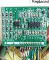
I got the big chip in above PCB, replaced it and the small one is heating up.
There is no dead short on the supply pins of the PCB but low R reading.
So need to wait for that chip to arrive.
 

Thread Starter

R!f@@

Joined Apr 2, 2009
10,007
Hey Guys.
Been quite a while. Lotta work on the Job.
Found a missing part couple of days back but was not able to attend.
Here is an update on the progress....
Controller.jpg

The 8 Pin IC went missing, so had to re-order. Both Chips and it's supply R is replaced.
Cannot find any other issue on it so far.

==================================================================

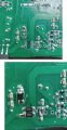
Burnt Components.jpg

Repaired the burned area with solder mask and replaced all the components. The Low R shunts are based on a guess the original value is not known as of yet.
D13 package is smaller, it's what I got from china. Hope it will hold. The number is same.

The PFC Power devices were soldered without sink to test.
Powered via variac just in case. Increased the voltage, no smoke. That was good sign but supply refused to start. :confused: .

Again, back to the drawing board.
Traced the PFC/PWM controller Supply and there was nothing. The Stby Supply is working. Jump the "PS ON" and opto switches but no Vcc.


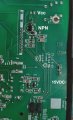
Control Supply.jpg

The"BL" denoted seems to be a NPN transistor.Collector has 24VDC, reduces to 15VDC when PS ON is active but emitter has no voltage when base drive is there.

AAAARGH ! :rolleyes:
It's late and tired and hungry........ gotta go junk diving to find a compatible one.

Till then ....C Ya.
 

Thread Starter

R!f@@

Joined Apr 2, 2009
10,007
Junk Diving gave me a 2SD1664 of the same package.
Swapped the "BL".
Powered up via variac,.
The control Vcc came at around 110VAC input.
Jumped the PS ON and there came a familiar SMPS startup sound.

PFC voltage jumped to 400VDC and main output was at available@37VDC. :).

It works. Just a bit skeptical on applying 220VAC input.
Need to make a bulb protection thingy on AC input before applying full voltage. Just to be safe.
Hard to find filament bulb these days.
 

Thread Starter

R!f@@

Joined Apr 2, 2009
10,007
Hey Guys.

220VAC was applied through a filament bulb. It glowed and went out.
Good sign.
Applied 220VAC direct and it works. Cycled for couple of times and all good

Turned PS ON and supply is active. no sound or ringing.
Now to test it with sound and drive it crazy.

I documented the voltages for future reference and to any one who might need it.
PS : Voltages marked in RED represent the readings taken while the Power Supply Unit (PSU) is actively running in the "PS ON" state.
 

Attachments

Top