 Facebook
 Google
 GitHub
 Linkedin
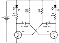
View attachment 263723
the circuit photo uploaded is blur. is it because of low resolution?where can I make resolution higher?
Mod: Adjusted the image.

the circuit photo uploaded is blur. is it because of low resolution?where can I make resolution higher?
Mod: Adjusted the image.
Last edited by a moderator:
") very good questions. If you read this thread in its entirety you'll find your answer it's a very common question and a very good read.
very good questions. If you read this thread in its entirety you'll find your answer it's a very common question and a very good read. 


