Temperature Sensor made with Transistors

Thread Starter

kiweered

Joined Dec 13, 2021
28
Hi !

For a school project I'm asked to design a temperature sensor with transistors exclusively.

I need to use the characteristics of a temperature-dependent transistor and implement a transistor(s) amplifier which will fix the sensitivity of the sensor.

I can only use bipolar and FET transistors, resistors and a continuous power supply +/- 15V.

For now I may have the first part of the project :
Capture d’écran 2021-12-13 à 10.14.59.png

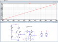
A bipolar transistor is adapted in impedance and the OUT of the circuit (Resistor R3) shows the following characteristic depending on the temperature :

Capture d’écran 2021-12-13 à 10.15.17.png

I am a bit lost and I'm only begining electronics. Is what I did right? How to fix the sensitivity of the assembly? Is there a way to be at 0V when T=0°C and/or make the OUT of the circuit more linear ? Do you have any idea how to make this sensor?

Thanks a lot for any help you can give me !
 

MrAl

Joined Jun 17, 2014
13,677
Hi ! Here is the .asc file


Thanks, I will look at this file
It looks like you might be using a single transistor to measure temperature which probably means you are doing something similar to what we do when we use a diode to measure temperature.
The diode temperature response is often taken as an approximation to be -2.2mv per degree C but i am not sure how accurate you have to get this for your class project as the response deviates from that to some degree in real life.
Very often diodes are used to sense temperature of power devices. They are mounted in close proximity to the device to be monitored. They dont expect perfect temperature tracking though they just need to detect some limit temperature like maybe 90 degrees C in which case they may shut the system down.
But as a full range temperature sensor, in the approximation you would work it as a linear problem with offset. In a more advanced version you should either look up more info on the diode/transistor response or take a real life transistor, put it in a home made oven, and as the temperature rises inside the oven log the response of the diode/transistor. You can then get an idea how to build your circuit better.
 

Thread Starter

kiweered

Joined Dec 13, 2021
28
hi kiw,
Look at this option.
E

Added 2nd image, shows improved correlation in Vout versus Temp'

View attachment 255080
Thanks a lot for your help. I understood that you are using a OP AMP to add an offset to put the 0V to 0°C. We are not allowed to use them but I believe it's possible to create a opamp with mosfet transitors... Anyway maybe it's ok for us to not have an offset.
What is the purpose of the 2 diodes D1 and D2 ? Why using 6V Vcc and not 15V ?

Diode connected transistors work well for this purpose.
You and MrAI are both talking about Diode based temperature sensors. We thougth about this in our first researchs. We will keep searching info. Thanks
 

Papabravo

Joined Feb 24, 2006
22,064
Thanks a lot for your help. I understood that you are using a OP AMP to add an offset to put the 0V to 0°C. We are not allowed to use them but I believe it's possible to create a opamp with mosfet transitors... Anyway maybe it's ok for us to not have an offset.
What is the purpose of the 2 diodes D1 and D2 ? Why using 6V Vcc and not 15V ?


You and MrAI are both talking about Diode based temperature sensors. We thougth about this in our first researchs. We will keep searching info. Thanks
Do you know what a diode connected transistor looks like? It is just a transistor with the base connected to the collector. I leave it to you to determine why this is a really superior idea. Think differential!

I know YT videos are poorly regarded for the most part, but there is one that might be worth a few minutes of your time, especially as the paper copy of this Jim Williams circuit is so hard to obtain

 
Last edited:

ericgibbs

Joined Jan 29, 2010
21,413
What is the purpose of the 2 diodes D1 and D2 ? Why using 6V Vcc and not 15V ?
hi kiwe,
The PNP transistor is configured as a constant current source, the two Diodes set the Base to Vss voltage. The R4 resistor sets the Constant current value.

You asked for 0Cdeg to give a Vout of 0V, but your temperature range is -50C through +150C, how is it possible to achieve this result by using a single +15V supply.
Any temperature less than 0C would have to give a negative Vout.
So for the purpose of the demo simulation and split the 15V into approx half, ie: +/-6V

The two diodes and the transistor Base/Emitter junction are being subject to the same temperature range.
Their absolute changes in Vfwd voltage tend to linearize the conduction of the PNP so produce a close to linear response, this is also a point you raised in your post.

Does that cover your query.?
E
 

MrAl

Joined Jun 17, 2014
13,677
Do you know what a diode connected transistor looks like? It is just a transistor with the base connected to the collector. I leave it to you to determine why this is a really superior idea. Think differential!

I know YT videos are poorly regarded for the most part, but there is one that might be worth a few minutes of your time, especially as the paper copy of this Jim Williams circuit is so hard to obtain

Hi,

I dont know if you realize you posted this but is this the same as a colonoscopy? (See actual screen shot below, ha ha)

But i agree, diode connected transistors are a little better than plain diodes. I think they are made slightly better than diodes.

ScreenShot_20211214_072820.jpg
 

Thread Starter

kiweered

Joined Dec 13, 2021
28
Hello !
I'm back sorry for the delay, I had school exams.

So... This is where we are now :
Capture d’écran 2022-01-11 à 16.37.25.png

We have the V(Dout) voltage which increase with temperature (as Vce decrease) and we want to amplify it with a common emmiter at Q3.

Capture d’écran 2022-01-11 à 16.37.44.png

V(Dout) signal is at least 8.4 V and Vbe of Q3 is approx. 0.7. so Q3 is correctly biased.
R6/R7 = 10

But it definnitly seems that the common emmiter is not working because V(out) is not amplify.
Any suggestion on how to amplify our temperature dependant signal ? (We are only allowed to use transistors and resistances)

Thanks a lot for any help.
 

Attachments

Thread Starter

kiweered

Joined Dec 13, 2021
28
hi k,
This is a Hint.
E
View attachment 257397
Hi,

I can compute that :
\[ V_{dout}=R_{12}\times I_B +V_{be}+ R_7\times I_e \approx I_c\times(R_{12}/\beta +R_7)+V_{be} \]
\[ V_{out}=V_{ce}+R_7\times(V_{dout}-V_{be})/R_7 \]

with the small signal dynamic analysis :
\[ V_{out}=-R_6\times I_b \]
\[ V_{dout}=V_{in}=(h_{11}+R_{12}+\beta R_7)\times I_b\]
\[ Gain = V_{out}/V_{in}=-R_6\beta /(R_{12} + h_{11}+\beta R_7) \approx -R_6/R_7 =10 \]

What I can understand and see is that
- R12 limits the current in the base and add an offset to V_{out}.

But I don't understand how it will affect the gain wich is suposed to be 10 with R6 and R7...

How did you do in the exams?
well hardly... I understand the principles of transistors electronic and I can analyse a basic transistor circuit. But it's really hard for me to design one :( the others school subjects went well !

Thanks again
 

crutschow

Joined Mar 14, 2008
38,389
I understand the principles of transistors electronic and I can analyse a basic transistor circuit. But it's really hard for me to design one
Yes, I remember it was somewhat of a shock when I was given the assignment to design some simple transistors circuits for my first electronics job, and I realized that most of my electronic schooling had been in analyzing circuits, not synthesizing them.
I had to look at much of application notes on circuit design, before I was able to do it (this was well before the Internet and Google, of course).
 

crutschow

Joined Mar 14, 2008
38,389
Is there a way to be at 0V when T=0°C and/or make the OUT of the circuit more linear ? Do you have any idea how to make this sensor?
If you use a diode connected transistor (e.g. a 2N2222) as a voltage sensor, biased at a constant 1/2 mA, or so, the collector-emitter voltage voltage change will be fairly linear with temperature.
You can then amplify and offset bias that output with a two transistor differential stage to give the output you want.
The details of that are left to you as an exercise, but I can answer any questions to help you with that.
 
Top