 Facebook
 Google
 GitHub
 Linkedin
Hi All,
Newbie here in need of some help.
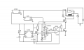
I am trying to make an adjustable temperature controller for a refrigerator to hold a temperature to an accuracy of about +/- 1°C by turning on and off the compressor when appropriate. I also want my circuit to delay turning on the fridge compressor for about 5 minutes after turning off to prevent damage.
I am using an LM293 Comparator to compare the output of an LM35 Linear centigrade temperature sensor to a voltage that I set as the reference. Positive Feedback introduces a 20mV hysteresis that corresponds to the +/-1°C accuracy that I want. Once the compressor goes low, this triggers a TLC555 timer in a monostable mode to turn off a MOSFET for 5 minutes, preventing the compressor relay to throw. This FET is "Anded" with a FET driven by the comparator. So basically, the compressor relay can only throw if the there is no Delay and the temperature measured is above the high threshold of the comparator.
Now my problems...
I am getting bad oscillations once the comparator goes low and then back high triggering the monostable 555. After a couple of seconds, I hear the relay periodically click like a clock, which is not what i want. Seems like the charging capacitor wants to discharge but is held high because of the trigger? From my understanding, once the comparator triggers the 555, the output of the timer should go high, turning off the FET directly under the relay for at least 5 minutes (after 5 mins, the timer will turn the FET back on when the comparator goes high again). Also, seems like changing the charge resistor on the 555 changes the threshold of the comparator. Setting the resistor to 0 makes the comparator behave more like expected. I have no idea why and it is driving me nuts.
Attached is a schematic. I omitted drawing the noise caps on the regulator but they are there -. 3.3uF on input .1 on output. Also have .1uF caps to the voltage supplies to all IC's. I also omitted pull down resistor on the FETs. Also attached is a schematic from the PCB which is a little harder to read but has more detail of whats on my actual board.
Thanks for any input.
Newbie here in need of some help.
I am trying to make an adjustable temperature controller for a refrigerator to hold a temperature to an accuracy of about +/- 1°C by turning on and off the compressor when appropriate. I also want my circuit to delay turning on the fridge compressor for about 5 minutes after turning off to prevent damage.
I am using an LM293 Comparator to compare the output of an LM35 Linear centigrade temperature sensor to a voltage that I set as the reference. Positive Feedback introduces a 20mV hysteresis that corresponds to the +/-1°C accuracy that I want. Once the compressor goes low, this triggers a TLC555 timer in a monostable mode to turn off a MOSFET for 5 minutes, preventing the compressor relay to throw. This FET is "Anded" with a FET driven by the comparator. So basically, the compressor relay can only throw if the there is no Delay and the temperature measured is above the high threshold of the comparator.
Now my problems...
I am getting bad oscillations once the comparator goes low and then back high triggering the monostable 555. After a couple of seconds, I hear the relay periodically click like a clock, which is not what i want. Seems like the charging capacitor wants to discharge but is held high because of the trigger? From my understanding, once the comparator triggers the 555, the output of the timer should go high, turning off the FET directly under the relay for at least 5 minutes (after 5 mins, the timer will turn the FET back on when the comparator goes high again). Also, seems like changing the charge resistor on the 555 changes the threshold of the comparator. Setting the resistor to 0 makes the comparator behave more like expected. I have no idea why and it is driving me nuts.
Attached is a schematic. I omitted drawing the noise caps on the regulator but they are there -. 3.3uF on input .1 on output. Also have .1uF caps to the voltage supplies to all IC's. I also omitted pull down resistor on the FETs. Also attached is a schematic from the PCB which is a little harder to read but has more detail of whats on my actual board.
Thanks for any input.
Attachments
-
 49.5 KB Views: 37
 -
 29.5 KB Views: 37


