Facebook
 Google
 GitHub
 Linkedin
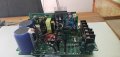
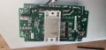
I have a 3ph Teco E510 that's stopped working with no warning. I am a very firm believer its the switching power supply just because it is 100% dead and thats almost what it always is. I may be incorrect.
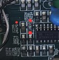
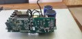
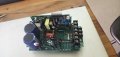
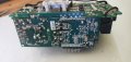
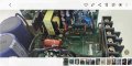
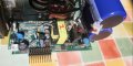
Its 400v 3ph input to this unit. The voltages inside are scary enough to not be wanting to be poking around too much without a plan on what I need to look at. I was hoping someone might give me a bit of assistance, what I can easily check to fault find. If it gets too difficult then its going in the bin but it might be a simple fix. I guess, with the 3ph input I am a little confused when I look at this board is all.
So, perhaps 4-5 messages with pictures is the limit? Would someone give me a hand? Oh. I am a registered Electrician and a EST. Just not super electronics biased. Thanks in advance. Let me know and I will post some pictures of this unit. I hate throwing stuff away.