Technics su x 101

Thread Starter

jeffOO

Joined Mar 8, 2020
25
Hi
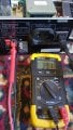
I have changed different speakers to try which one suit to amp.
I ending up with 2 speakers blown up and my amp left side terminal not working.
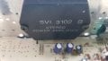
Amp is Technics su x 101.
Blown up speakers is sansui sb series. 12" .
Now I am really scare to connect with left speakers terminal.
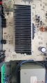
Amp is working fine except left terminal.
I am only basic electrical knowledge.

Any suggestions will be very helpful and appreciate it.


Jeff
 

MrChips

Joined Oct 2, 2009
30,806
Don't connect any more speakers if you don't want to blow them.
Disconnect all speakers until the problem is fixed.
There is DC imbalance in the output amplifier. Measure the DC voltage across the output + and - terminals.
 

Thread Starter

jeffOO

Joined Mar 8, 2020
25
Don't connect any more speakers if you don't want to blow them.
Disconnect all speakers until the problem is fixed.
There is DC imbalance in the output amplifier. Measure the DC voltage across the output + and - terminals.
Hi
Thanks for your help.
I got R terminal 128.5 mv
L terminal 00.4 mv
It's not right ?
Should be same?

Jeff
 

MrChips

Joined Oct 2, 2009
30,806
Neither voltage readings are high enough to blow your speakers.
Do you have any resistors that you can connect on the outputs? 5 - 20 ohms should do.
 

Thread Starter

jeffOO

Joined Mar 8, 2020
25
Hi
Thanks for replying.
I can get from shop.
When measure it power on or off?
Left side terminal 39.1 mv
Right. _ 05.0 mv
With power on.
 

MrChips

Joined Oct 2, 2009
30,806
What is the point of measuring with the power off?

Again, those voltages are not enough to blow speakers.

If you have capacitors, 100 - 1000μF / 50V you can put in series with the speaker you would not blow the speaker (just for testing).
 

MisterBill2

Joined Jan 23, 2018
18,502
It is obvious that we are lacking a whole lot of information about the situation, and also quite clear that the TS may not be able to provide the information.
It is certainly correct that the claimed measured voltages will not damage a speaker, and so either the measurements are incorrect or else the conditions are different at the time the measurements are made. Also, are those AC or DC voltage measurements? And what sort of meter is being used? there may be 100 volts DC and only millivolts of AC signal present. In addition, there may be a failed meter lead involved. I have had that problem myself. A failed meter lead can be a very bad problem.
 
Last edited:

MisterBill2

Joined Jan 23, 2018
18,502
Once again, given the impossible results reported, I suggest first verifying the correct functioning of the meter system. Those results are not reasonable, so there must be a failure of some kind.
 

Thread Starter

jeffOO

Joined Mar 8, 2020
25
Once again, given the impossible results reported, I suggest first verifying the correct functioning of the meter system. Those results are not reasonable, so there must be a failure of some kind.
Hi
Thanks for all your reply.
I tested another cheaper speaker.
It works on R terminal.
Left terminal just noise no music at all.
I measured DC voltage.
Any help would be appreciated.
Jeff
 

Attachments

MisterBill2

Joined Jan 23, 2018
18,502
Hi
Thanks for all your reply.
I tested another cheaper speaker.
It works on R terminal.
Left terminal just noise no music at all.
I measured DC voltage.
Any help would be appreciated.
Jeff
Try also measuring the AC voltage across the same points. On an audio amplifier there should not be very much DC voltage, nothing beyond a few millivolts. This amplifier uses a module for the output section. Are you sble to inspect that area for failed parts?
 

MrChips

Joined Oct 2, 2009
30,806
The output power amplifier is a Sanyo/Panasonic SVI 3102B hybrid module.
It is a stereo amplifier with two channels, Left and Right channel.
If you swap the input signals to the power module it will allow you to determine if the module is at fault.

Try exercising all the program selector switches and try input from all possible sources. Interchange Left and Right channels where ever you can.
 

Thread Starter

jeffOO

Joined Mar 8, 2020
25
Try also measuring the AC voltage across the same points. On an audio amplifier there should not be very much DC voltage, nothing beyond a few millivolts. This amplifier uses a module for the output section. Are you sble to inspect that area for failed parts?
AC 13.90 v
It's very much plain.
I am not sure where to start.
Thanks for your time.
Also
I have changed input channel. Cd .aux they are same result.
Thanks
 

Attachments

MrChips

Joined Oct 2, 2009
30,806
Take a look at the main board and locate the two jumpers I have coloured in green and red.

With the power off and unplugged, cut both jumpers in the middle of each and cross connect the jumpers, i.e. red to green and green to red.

Check which channel works now.


Technics_SUX101_01.jpg
 

LesJones

Joined Jan 8, 2017
4,190
Looking at the third picture in post #10 the reading between the speaker terminals is 39.1 volts. That is enough to destroy a speaker. I Think The most likely cause is the power amplifier module but I suggest first checking the voltage on the input pins of the amplifier module (Pins 11 (left) and 14(Right)) with respect to ground in case one of the input DC blocking capacitors is leaky. They should both be very close to zero volts. (One is for each channel.

Les.
 

MrChips

Joined Oct 2, 2009
30,806
Going beyond what Les has suggested, measure and report the DC voltage with respect to GND at all 14 pins on IC501.
Make sure that you do not short adjacent pins with your meter probe.
 

Thread Starter

jeffOO

Joined Mar 8, 2020
25
Hi
Thank you for your time. Who replying to me especially Mr Chips, Mr LesJones, Mister Bill2.

I measured C501 from left to right.
4.8mv. 39v. 39.2v. 39.3v. 13.46v. 47mv. 4.36v. 14.3v
0.2mv. 14.35v. 13.75v. 0.1mv
6.7mv. 2.4mv
Thanks again.

Jeff
 
Top