Technics SU-V5 won't turn on

Thread Starter

Ramska

Joined Jan 30, 2022
20
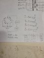
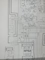
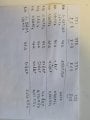
Hello! I am new to the forum, and I don’t have a lot of background in electonics... My Technics SU-V5 amplifier was working properly, and then suddenly went off, and I couldn't turn it back on. There was a slight smell of burnt. I would like to try and repair it myself if it is feasible (and also because I can't find someone to look at it here in Montreal !). I have the schematic diagram. So I opened it and the T3.15A fuse was blown. I changed it, and it blew again when I turned the amplifier on... I cheched the input power selector and it's in the correct 110V position. I checked with a multimeter and the input selector seems to be ok (although it seems that the indicated position 110V gives 120, 120 gives 110, 220 gives 240 and 240 gives 220, which is odd…).
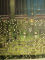
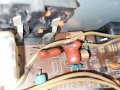
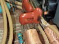
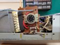
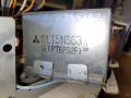
I checked the transformer (SLT5N363), I got about 3.5 Ohms between the relevant pins (I think) at primary, and about 0.6 Ohms at secondary… I don’t know about the values, but least I didn’t get 0, so I guess it is ok ? Any idea what I could check next ? Can a shortcut at secondary somewhere make the primary fuse pop ? Visually, I didn't notice anything burnt, but I'm not sure where or what to look for other than help!
 

Attachments

MrChips

Joined Oct 2, 2009
30,824
Bonjour! Welcome to AAC!
First stop would be to check the power supply rectifiers and smoothing capacitors.

The four rectifiers are D601-D604.
The two capacitors are C601 and C602, 8200μF/ 56V.

If you need more assistance just ask.

Technics SU-V5 PSU.jpg
 

Thread Starter

Ramska

Joined Jan 30, 2022
20
Thanks MrChips!
Dumb question maybe.. do I have to unsolder each component to test them or is there a trick?!
The results are in the picture below. It seems D603 and D604 are swapped on the schematic as on the board, they are not directly connected to each other. I get voltage on each diode in both direction. Do I need to unsolder them to confirm they are blocking in one direction? C601 and C602 both give me OL... is that what's wrong?
 

Attachments

MrChips

Joined Oct 2, 2009
30,824
Before you start unsoldering components, take the measurements in-circuit.
Set your DMM to diode range.
Measure across each diode, one at a time. Do it again with meter probes reversed.
Report your readings.

Edit: Sorry, I just saw you posted results.
 

Thread Starter

Ramska

Joined Jan 30, 2022
20
If you smelled something burning, can you look it over closely and try to find what burnt?
So.... I found something suspect, I hope this is the issue! I found this Z304 that seems to be a capacitor and a resisitor in series, that has a dark stain on it, and that started to melt the brown wire J11 next to it. I checked the wire and the sheath is not completely removed. What shoud I do? Unsolder that component and test it? What test should I do?
I hope this is it, I didn't really found anything else abnormal...
Thank you!!
 

Attachments

MrChips

Joined Oct 2, 2009
30,824
You would be very lucky if there were a single component blown that just needs to be replaced.
Prepare yourself for a very long journey of electronics diagnostics ahead of you.

You are in a difficult situation when the fuse blows. Almost any remedy you try to install will end up with more blown fuses.
I hope you have a lot of spare fuses.

One technique often used is to build a current limiter using a lamp bulb to be placed on the AC input to the technics.

Here is a schematic courtesy of AAC member Delta Prime:
Reference:
https://forum.allaboutcircuits.com/threads/stage-line-500w-amp-repair-help-please.176128/
1644109353548.png

The next step after this is to remove the four output transistors Q331/Q333 and Q332/Q334 and test them.
We'll get to that shortly.
 

Thread Starter

Ramska

Joined Jan 30, 2022
20
Would you know a website where I can procure this z304 component? I don't even know how it's called! Does the marking mean that the capcitor is 473microF and the resistor is 10 Ohms, and that they see 50V? Is there any chance that I find such compnent somewhere?
 

sghioto

Joined Dec 31, 2017
5,392
You could make one. It's a .047uf cap in series with a 10 ohm resistor.
Most likely used as a spurious high frequency filter on the audio output.
 

MrChips

Joined Oct 2, 2009
30,824
Before you go that route, get out your DMM and set it to the lowest ohm range.

Turn off the power. Unplug the unit.
Disconnect all loudspeakers.

Measure the resistance from TP1 to the positive supply rail and to the negative supply rail.
Reverse the DMM probes and take two more measurements.

Do this also for TP2, TP3, TP4.

We are looking for a blown transistor which will show up as a short.
 

Thread Starter

Ramska

Joined Jan 30, 2022
20
Before you go that route, get out your DMM and set it to the lowest ohm range.

Turn off the power. Unplug the unit.
Disconnect all loudspeakers.

Measure the resistance from TP1 to the positive supply rail and to the negative supply rail.
Reverse the DMM probes and take two more measurements.

Do this also for TP2, TP3, TP4.

We are looking for a blown transistor which will show up as a short.
I am not exaclty sure what the positive and negative rails are, so I'm going to assess that negative is the zero that I can find a point 13 of SUP22610E, and positive is either point 11 or point 15 of that same transformer output. Let me know if it is something else!
 

MrChips

Joined Oct 2, 2009
30,824
No. Negative rail will be measured as a negative voltage with respect to 0V common.
Post clear well focused photos of top and bottom sides of the board and we will show you your test points.
 

Thread Starter

Ramska

Joined Jan 30, 2022
20
No. Negative rail will be measured as a negative voltage with respect to 0V common.
Post clear well focused photos of top and bottom sides of the board and we will show you your test points.
I tried TP2 (TP302) and TP3 (TP304) to the transfo output, I get 0.0ohm bit 2 seconds later it increases to OL. Same result if I use loc 11, 13 or 15 of transfo output. Same thing when reversing DMM probes.
 

Attachments

MrChips

Joined Oct 2, 2009
30,824
You are probably charging the storage capacitors by attempting to take a resistance measurement.

The meter measures resistance by measuring current. The capacitor takes an initial charging current which then decreases to zero as the capacitor becomes fully charged. Hence the resistance measurement shows low resistance and finally open circuit. This is normal when metering across a capacitor.
 

MrChips

Joined Oct 2, 2009
30,824
On the solder side (bottom side) of the PCB you will find four power transistors (two shown in the photo below).

Measure the resistance between the E and C pins with the Ohmmeter one way and then reversed.
Do this for all four transistors.

Technics SU-V5 output transistors.jpg
 

Thread Starter

Ramska

Joined Jan 30, 2022
20
On the solder side (bottom side) of the PCB you will find four power transistors (two shown in the photo below).

Measure the resistance between the E and C pins with the Ohmmeter one way and then reversed.
Do this for all four transistors.

View attachment 260549
Not easy to measure! It all kept changing except for Q333 that is 0.4 Ohms in both directions. I took several measures, tried to take the initial value and if increasing or decreasing... does it make sense?!
 

Attachments

MrChips

Joined Oct 2, 2009
30,824
Well it does. Q333 is the smoking gun we're looking for and needs to be replaced.

Q333 is transistor 2SA1106
Q331 is transistor 2SC2581

Instead of buying a single transistor you may as well buy a set in pairs because we don't know how many times they will blow before getting the amp fixed. You can take a chance and buy it off Amazon.

Edit: After you receive replacement parts, wait for instructions before proceeding.
 

Thread Starter

Ramska

Joined Jan 30, 2022
20
Well it does. Q333 is the smoking gun we're looking for and needs to be replaced.

Q333 is transistor 2SA1106
Q331 is transistor 2SC2581

Instead of buying a single transistor you may as well buy a set in pairs because we don't know how many times they will blow before getting the amp fixed. You can take a chance and buy it off Amazon.

Edit: After you receive replacement parts, wait for instructions before proceeding.
Thanks! I ordered a couple, I'll let you know when I get them. In the meantime I removed the filter Z304 to replace it. I tested it in capa mode and got about 50 nF. I tested in ohmmeter and got OL. It seems the resistor blew up.. I thought it was the capa. So I cant find this component online, what do I need exactly to replace it? A 47nF 50v ceramic radial capa? And a 10 ohms resistor? What power shoud I get(it seems there is 1/4 W or 1/2 W or else)?
 

MrChips

Joined Oct 2, 2009
30,824
Thanks! I ordered a couple, I'll let you know when I get them. In the meantime I removed the filter Z304 to replace it. I tested it in capa mode and got about 50 nF. I tested in ohmmeter and got OL. It seems the resistor blew up.. I thought it was the capa. So I cant find this component online, what do I need exactly to replace it? A 47nF 50v ceramic radial capa? And a 10 ohms resistor? What power shoud I get(it seems there is 1/4 W or 1/2 W or else)?
How do you know that it is bad?

50nF is acceptable for 47nF.
OL is the expected reading on an Ohmmeter. You cannot expect to read 10Ω because it is in series with a capacitor.
 

abrsvc

Joined Jun 16, 2018
138
When checking the amp, leave the center pin of the transistors disconnected. Power up the amp and take measurements of the 3 pads. With the center pin NOT connected, the voltages should read correctly without any current flow. This is a shortcut way to verify that the driver sections are OK too. You won't blow the power transistors this way.
 
Top