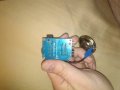
Team Fortress 2 Mini Sentry

bertz

Joined Nov 11, 2013
327
OK, my young friend. The mail just came, but without the MP3 module. I was hoping it would be there so I could test it and make sure my wiring instructions are correct. Hopefully it will come tomorrow. Meanwhile, we are heading up to the cabin in the morning and wont be back until Sunday. So, I am attaching a wiring diagram and a set of instructions as complete as I can make them for now to help get you started. Remember to work this wiring diagram with the CH1030A data sheet available here:

http://www.picaxe.com/docs/CHI030A.pdf

Good luck and I'll look in on you again on Sunday to see how you're progressing.
 

Attachments

bertz

Joined Nov 11, 2013
327
I really haven't spent any time at all working on the software for this project, and I don't anticipate that I will be able to devote too much time to software for the next couple of weeks. I am going to suggest that you open a thread on the Picaxe forum:

http://www.picaxeforum.co.uk/forumdisplay.php?2-Active-PICAXE-Forum

Post the wiring diagram and clearly describe what you want the sentinel to do. They are a great bunch of guys over there and they are wizards with Picaxe Basic. To get you started I have attached some code that you will also want to post on their site. Basically it defines the inputs and outputs as well as incorporates a little routine to move the turret back and forth. Good luck!
 

Attachments

Thread Starter

Blargenth

Joined Apr 30, 2015
45
Thank you for all the help Bertz, I can't wait to see this project all the way through.

Anyways I have a project update... WOOD WORKING IS NOT MY FORTE!

I spent all last night trying to make the tripod I wanted to put the sentry on out of wooden dowels I had and well... Its hard to clamp two things together at a 45 degree angle... so I had to hold the first leg on for 30 minutes.... only to have it fall off during trying to get the second leg on.

And while yes there were probably easier ways to do that, I either don't have the tools for it or don't have the experience to do it well enough.....

So I'm abandoning wooden legs. for a PVC tripod!
 

Thread Starter

Blargenth

Joined Apr 30, 2015
45
Got alot of the painting done on the pvc parts, still waiting for the battery packs to come in so I can look into programming the board as well as start wiring everything up. And also need to cut out all the fittings for the servo, led, and speaker so that I can paint the main sentry body and then start putting this bad boy together.

I also have had plenty of chances to skim over your instructions, wiring diagram and code snippet... and I can't thank you enough for all the help you've given me on this project. I'm sorry that I can't pay you but I will definitely be sure to mention this forum as well as you whenever anyone at the convention asks how I made this. And on top of that please let me know if their's anything I can do to repay you.
 

bertz

Joined Nov 11, 2013
327
Now that I have had a chance to check out the MP3 module, I have revised the wiring diagram and instructions. Nothing major, just wanted to make sure it was clear and not misleading. I did download some sound effects and it works quite well. However you absolutely will need an amplifier and larger speaker.

I noticed that you logged on to the PICAXE forum and Rick has taken an interest in your project. Your in good hands. :D Rick has been a great help to me on other projects I have worked on.

I'll be busy with the festival for the rest of this week and then it's off to the Redneck Riviera. Good luck!o_O
 

Attachments

Thread Starter

Blargenth

Joined Apr 30, 2015
45
I'm getting bits and pieces of the soldering done each day. But I don't have my own voltmeter so I can't test my welds at the moment. My roommate's uncle has one and he's gonna try and borrow it for me, but until then I don't feel safe even powering the board up.
 

elec_mech

Joined Nov 12, 2008
1,500
You can pick up a new multimeter for under a buck: find the nearest Harbor Freight in your area, print this, buy something for under a buck, and get a free multimeter. It's not the best in the world, but it will do the job. However, test it before you leave the parking lot. I've gotten some where the leads don't stay secure in the meter - just perform a resistance test and spin the plugs a little to verify the connection is solid. If not, go back into the store and exchange it for another one.
 

Thread Starter

Blargenth

Joined Apr 30, 2015
45
So I finished wiring the whole thing up... and I finally put in the batteries for its first run.... and All it did was make the servo twitch a smidge on startup. Ontop of that, I started to smell the worst circuitry smell, electric smoke coming from the central pick board. I'm afraid to turn it on again for fear that I wired something wrong, and I tried plugging it into the pickaxe editor to try seeing if it detected my board... but nothing but the 'usb not recognized' sound happened. I have no idea how to tell in pickaxe if my board is working...
 

elec_mech

Joined Nov 12, 2008
1,500
It's kind of hard to make out the connections from the pictures, but let's start with the basics.

It looks like the power leads are reversed on the receiver board. I see a red wire going from the GND connection on the receiver board into what appears to be V1+ on the PICAXE board. I see a black wire going from 5V on the receiver board to what I assume is the battery ground.

  1. Did you remove the small batteries that came with the audio board? It appears so, but I want to make sure. I learned the hard way that if you connect external power or the USB cord to load the music, the batteries will be 'charged' and self-destruct.
  2. Remove everything from the PICAXE board. Remove power from all the other boards.
  3. Use a multimeter to check resistance (if it has multiple resistance settings, use 200Ω) of the power connections on the PICAXE board. Again, no power should be connected to the PICAXE board at this point. You should see either a high resistance or nothing (OL). If you see something below 1000, you might have a short. If you see something below 10, you definitely have a short.
  4. If you don't see a short, set the multimeter to read DC voltage. If you have multiple settings, choose 20VDC.
  5. Connect the red probe to + and the black probe to - on the power terminals/wires (whatever you are using to power the PICAXE board - again, this should not be connected to the PICAXE board at this time). You should see something between 4.5 to 5VDC. If you see anything higher, there's a problem.
  6. If everything is okay so far, connect the power supply to the PICAXE board. Repeat step 5 and verify the power going to the PICAXE board is still between 4.5 to 5VDC. I suggest putting the red probe on leg 14 of the PICAXE IC and the black probe on pin 5. These are the power legs of the PICAXE (assuming you're using an 18M2).
  7. Still good? Then the problem is/was likely a power connection to one of the other boards. Before you do anything else - again, assuming everything you've done so far is working as expected - connect the USB programming cord and, with power applied to the PICAXE board, try to write a program to the PICAXE. Does it work?
  8. If yes, remove power and connect one of the external circuits, let's start with the LED circuit. Double-check your connections and apply power. Does the LED light? If yes, repeat for each of the other parts, one at a time, removing power before you connect anything, then seeing if that part works before connecting the next one.
 

Thread Starter

Blargenth

Joined Apr 30, 2015
45
Ok, I got to step 6, everything is unhooked save for the poer and the ground wire coming out of pin G. I touched the probes to each power terminal for the pickaxe board and got 2.84 back. Ontop of that my finger happened to be holding onto the board close to its main chip

This one
IMG_20150710_163504[1].jpg

And it was on fire! it was too hot to touch!
 

elec_mech

Joined Nov 12, 2008
1,500
Ooo . . . look at the orientation of the IC's. The hot one (I assume this is the 18M2) appears to be installed backwards. If that is the case, power is going to the wrong legs which might explain the heat. Take a look at the board manual. I think this is it. Unfortunately, it sounds like the PICAXE might be toast. Won't hurt to turn it in the proper orientation and redo step 6 and see if power is going to the right legs.
 

Thread Starter

Blargenth

Joined Apr 30, 2015
45
I turned it around. Its not heating up. Also I may just be blind but I can't figure out where leg 14 and 5 are. On the circuit diagram it shows them at the top and bottom but I can't figure out where they connect on the board...
 
Last edited:

elec_mech

Joined Nov 12, 2008
1,500
Look for the indentation in one end of the PICAXE. With the indentation facing away from you (let's call the indentation end the top), the first pin on the top left is pin 1. The pin below that is pin 2 and so on. The last pin on the bottom left is pin 9. Opposite pin 9 on the right side is pin 10. So with the indentation on top, the pin on the top left is pin 1 and the top right pin is pin 18. Take a look at the pinout for the 18M2 here.
 

Thread Starter

Blargenth

Joined Apr 30, 2015
45
SHE LIVES! no one told me I had to get drivers for the download cable. Now the chip is detected and she seems to be working
 
Last edited:

Thread Starter

Blargenth

Joined Apr 30, 2015
45
Running into another problem. I just ran a 20v test on the power out and ground going into the 200s mp3. All I got was .40v back. And when I tested the terminals touching the corner of the 200s board it didn't return a voltage.

Also I'm not sure if I hooked up the power to the amplifier correctly. When I switch it on the amplifier does light up a red led... but I noticed that isn't the only led on the board... and I can't find any documentation to confirm what that led means.

And to make things worse I think I shorted out the reciever chip... I mixed up the ground and the voltage wires by mistake... any idea on how to test if its still good or not?
 
Last edited:

elec_mech

Joined Nov 12, 2008
1,500
Running into another problem. I just ran a 20v test on the power out and ground going into the 200s mp3. All I got was .40v back. And when I tested the terminals touching the corner of the 200s board it didn't return a voltage.
I'm confused. The MP3 module should only have between 4.5 to 5VDC applied to it. 20V will kill it. Are you saying you applied 20VDC and you're not seeing voltage (which I'm also a bit confused by)?

Since you had a few things go wrong all at once, I suggest you step back and test everything individually. So for the MP3 player, remove all wires. Make sure all the batteries are removed. Reconnect the speaker to the MP3 board. Note that the speaker has a positive and negative connection, so be sure to reconnect it with the correct polarity. With only the speaker wired to the MP3 board and nothing else, connect a USB cable between the MP3 board and your computer and try to upload a file. If it works, the MP3 module is probably okay. Next, use a paperclip to test the MP3 module. Touch the paperclip across the two terminals called out as P0 and see if something plays through the speaker. Repeat for P1 - P4. If a file loads, but there is no sound, remove the USB cable and check the speaker connections. If unsure about polarity, go ahead and reverse the two wires going to the speaker then connect the USB cable (for power) and try the paperclip again.

Also I'm not sure if I hooked up the power to the amplifier correctly. When I switch it on the amplifier does light up a red led... but I noticed that isn't the only led on the board... and I can't find any documentation to confirm what that led means.
What is the number on the IC on the amp board? The thing attached to the heatsink? Can you post a picture of the bottom of the board as well? Are you using the speaker that came with the MP3 board to connect to the amplifier? We need to verify the impedance is a match. I also worry about the speaker handling the power the amp will give it. What value is on the back of the speaker, e.g., 4Ω, 8Ω, 16Ω, etc.? What is the wattage rating? It will be a number followed by W.

And to make things worse I think I shorted out the reciever chip... I mixed up the ground and the voltage wires by mistake... any idea on how to test if its still good or not?
Make sure you correctly connect the power (5VDC). Connect a meter between the GND pin and the D0 pin set to 20VDC. You should see 0V on the meter. Keeping the probes connected to the GND and D0 pins, press and hold the A button on the remote. You should now see about 5VDC on the meter. If not, try the other buttons, one at a time. If none of the buttons give you 5VDC, the receiver may be toast - don't feel too bad, I've got at least two that I've cooked accidentally in the last year or so. Try GND & D1, then GND & D2, and GND & D3 as well.
 

Thread Starter

Blargenth

Joined Apr 30, 2015
45
I'm confused. The MP3 module should only have between 4.5 to 5VDC applied to it. 20V will kill it. Are you saying you applied 20VDC and you're not seeing voltage (which I'm also a bit confused by)?

Since you had a few things go wrong all at once, I suggest you step back and test everything individually. So for the MP3 player, remove all wires. Make sure all the batteries are removed. Reconnect the speaker to the MP3 board. Note that the speaker has a positive and negative connection, so be sure to reconnect it with the correct polarity. With only the speaker wired to the MP3 board and nothing else, connect a USB cable between the MP3 board and your computer and try to upload a file. If it works, the MP3 module is probably okay. Next, use a paperclip to test the MP3 module. Touch the paperclip across the two terminals called out as P0 and see if something plays through the speaker. Repeat for P1 - P4. If a file loads, but there is no sound, remove the USB cable and check the speaker connections. If unsure about polarity, go ahead and reverse the two wires going to the speaker then connect the USB cable (for power) and try the paperclip again.


What is the number on the IC on the amp board? The thing attached to the heatsink? Can you post a picture of the bottom of the board as well? Are you using the speaker that came with the MP3 board to connect to the amplifier? We need to verify the impedance is a match. I also worry about the speaker handling the power the amp will give it. What value is on the back of the speaker, e.g., 4Ω, 8Ω, 16Ω, etc.? What is the wattage rating? It will be a number followed by W.


Make sure you correctly connect the power (5VDC). Connect a meter between the GND pin and the D0 pin set to 20VDC. You should see 0V on the meter. Keeping the probes connected to the GND and D0 pins, press and hold the A button on the remote. You should now see about 5VDC on the meter. If not, try the other buttons, one at a time. If none of the buttons give you 5VDC, the receiver may be toast - don't feel too bad, I've got at least two that I've cooked accidentally in the last year or so. Try GND & D1, then GND & D2, and GND & D3 as well.
For the mp3 player I didn't run 20 volts through it, I tested it with 20VDC. as for the amplifier and the speaker, the speaker is 32ohms and 0.5w.
I dunno what you mean by IC but the number on the thing attached to the amplifier is TDA7297, 8806E501. I've included a pic of the underside of the board.
11140060_974705965884218_8106805560729435541_n.jpg

as for the reciever testing, I'll try it later when I get my hands on my room mates multimeter.
 

elec_mech

Joined Nov 12, 2008
1,500
For the mp3 player I didn't run 20 volts through it, I tested it with 20VDC.
I'm missing something there. I don't know how you "test" with 20VDC but not supply 20VDC. Do you mean you have a 20VDC supply that is converted to 5VDC then fed to the MP3 board? I'm sure we're just not speaking the same lingo and something is getting lost in translation.

I dunno what you mean by IC but the number on the thing attached to the amplifier is TDA7297, 8806E501.
The IC number is TDA7297. You can take a look at the datasheet here. I also found a product page here. Unfortunately, it's next to useless since they have no real information. In looking up info on the TDA7297, it appears to work with speakers with an impedance of 4 to 8Ω, so the 32Ω won't work. Do you have an old desktop computer? They often have 8Ω speakers in them that should work for this project. The wattage won't be very high though, so if you really want to be able to hear and use the amplifier to its full potential, look for an 8Ω speaker rated around 10W.

I assume the red LED is there to let you know power is going to the amp. What voltage are you supplying the amp board?

Alternately, you could try skipping the amplifier and using a pair of battery-operated computer speakers.
 
Top