Teac AG980 receiver won't turn on

Thread Starter

sean5302

Joined Jul 26, 2021
25
Two silly questions:

1) Is the POWER switch on the front panel pressed in?
2) Did you check fuse FS101?
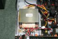
Yes, the power switch is pressed in and the fuse FS01 is OK.
I know power is getting to the unit because there are tiny LEDs on the front panel. One lights up when in standby and on pressing the standby/ on button the standby LED goes out and the 2 LEDs below light up, marked A/B and C/D
 

Thread Starter

sean5302

Joined Jul 26, 2021
25
Sean, Re your post #23. In the last line that post you tested the voltage on the pins of CP108 WITH RESPECT TO MAINS NEUTRAL.
I can't understand the reasoning for doing that test. What was it supposed to show ?
Did you check the continuity of fuse FS101 ?
With the unit UNPUGGED FROM THE MAINS unplug the connector to CP110 and measure the resistance between the two pins of the plug that plugs into that connector. (The part with two wires going to it.) (These wires will connect to the primary of the large transformer.)

Les.
The resistance is 7.0MegOhms between both pins of the lead from CP110.
FS01 is OK and there are LEDs on the front panel showing whether it's in standby or on. These change with each press of the standby switch.
My reasoning was that the unit is double insulated. The metal chassis should be isolated. I thought the ground would be mains neutral. I realise that was silly.
I have never done anything much with electronics and really value this opportunity to learn from experts here.
 

LesJones

Joined Jan 8, 2017
4,191
From the reading of 7 meg ohms it looks like the primary winding of the large transformer is open circuit. (I would have expected a reading in the tens or low hundreds of ohms.)
Can you follow the two wires from plug that plugs into CP110. I expect them to go directly to the large transformer. If they go via any other components or connectors they could be the cause of the fault. The most likely cause of this fault is a thermal fuse embedded in the transformer windings. Sometimes the thermal fuse is on the outside of the winding and can be replaced. If it is a thermal fuse that has failed it has probably been caused by a fault in the amplifier causing it to draw too much current but not so much to blow fuse FS101. A replacement transformer will probably be quite expensive and is probably not available as a spare part.

Les.
 

Thread Starter

sean5302

Joined Jul 26, 2021
25
Oh, that's disappointing but likely.
The unit has come from a local care home in the village. It's mainly full of very elderly ladies who were played music pretty much all day long. They're very upset now.
I suppose the transformer could well have died. I attach some pictures.
 

Attachments

LesJones

Joined Jan 8, 2017
4,191
It doesn't look like there is any possibility of getting to the thermal fuse (If there is one.) as the primary is closest to the core. I was hopping that the bobbin was in two sections with section for the primary and the other for the secondary.

Les.
 

Thread Starter

sean5302

Joined Jul 26, 2021
25
I may have to be destructive with the transformer. I've just phoned a transformer rewinds place and they want over £100 just to look at it. I have mechanical skills so will attempt to locate and bypass the thermal fuse. I might get a replacement as I really don't want to burn the care home down.
Very grateful to everyone here. Thanks.
 

LesJones

Joined Jan 8, 2017
4,191
I don't think it is practical to repair the transformer. It is probably varnished which means that getting the laminations apart will be very difficult. After that you would have to unwind the secondary winding. I think there is also another secondary winding as there are two thin orange wires coming from the transformer which I think are for the heater on the fluorescent display.

There are two of these receivers on ebay that might work out cheaper than repairing your unit.

Les.
 

MrChips

Joined Oct 2, 2009
30,824
Before destroying the transformer I would trace for 230VAC.
Set your DMM to 600VAC.
You have to be very careful here because one slip of the probes can have disastrous consequences.

Look for 230VAC between pin-1 and pin-2 at CP110.

I would not disconnect the plug at CP110 because poking meter leads into the socket is too risky.
Instead, I would leave the plug in the socket and stick two single strand insulated hook-up wire where the two yellow wires enter. Wrap the wires around the meter leads and keep your hands away while you try to power the unit.
 

twohats

Joined Oct 28, 2015
447
Les, Good work!
Sean, you are doing good!
Re; 110v ac I did highlight it in post #15 & #38
Using mains neutral as ground will give 110v ac almost any where. Half 220~ 230v ac

Edit: Forgot to mention MrChips, sorry. Good work too.
 

Thread Starter

sean5302

Joined Jul 26, 2021
25
Before destroying the transformer I would trace for 230VAC.
Set your DMM to 600VAC.
You have to be very careful here because one slip of the probes can have disastrous consequences.

Look for 230VAC between pin-1 and pin-2 at CP110.

I would not disconnect the plug at CP110 because poking meter leads into the socket is too risky.
Instead, I would leave the plug in the socket and stick two single strand insulated hook-up wire where the two yellow wires enter. Wrap the wires around the meter leads and keep your hands away while you try to power the unit.
I appreciate the safety concerns. I have already tested for 230V ac at CP110 and it's present.
The transformer was effectively destroyed yesterday because the laminated core was spot welded onto the base plate which I drilled to remove the plate.
I then found the laminated core glued together by a thick resin and had to force every plate apart before removal. After around 15 minutes I had exposed the coils and found a thermal fuse buried underneath them. It was open circuit.
In theory, I could rebuild the transformer but it wouldn't look pretty and there's around 60 old ladies who could be imperilled if it caught fire.
I may have to put my hand in my pocket and buy them a replacement. That's not going to be easy because this Teac had the facility to select different inputs and pipe the outputs to 4 sets of speakers in different locations. I haven't seen that before.
 
Top