TEAC A-3300SX-2T capstan solenoid circuit help

Thread Starter

minkey01

Joined Jul 23, 2014
185
Hi. Could someone help me that is good with reel-to-reel schematics?

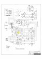
I want to copy the circuit of this capstan solenoid out of my TEAC A-3300SX-2T.

I highlighted the solenoid in the attached jpeg. Pdf attached too, if full schematic needed. I will be building this new circuit with new parts and just want a manual standalone switch to activate the solenoid. Using the same power supply too. Disregard everything else.

Imagine I just have the power supply and the solenoid. Now I need the circuit.

Anyone able to highlight the paths on the circuit that I will need to extract?

Thanks for the advice!
 

Attachments

Thread Starter

minkey01

Joined Jul 23, 2014
185
Someone extracted this solenoid circuit from the original schematic. See attached circuit jpeg. This solenoid should activate when you throw the switch shown on the right. It will remain activated until you turn the switch off. This is suppose to contain a timing circuit that gives the solenoid an initial extra boost to pull it in and then drops the volts when it is seated in order to save power and minimize heat.

What do you think of it? Will this work? Do you see any mistakes or problems?

I'm still searching for the missing specs on some of the parts on the parts list.

Can anyone recommend a relay part # for the k9 spot. It is suppose to give the solenoid the initial extra boost to activate and then drop after the solenoid is seated.
solenoid circuit_v4.jpg
 

GopherT

Joined Nov 23, 2012
8,009
Someone extracted this solenoid circuit from the original schematic. See attached circuit jpeg. This solenoid should activate when you throw the switch shown on the right. It will remain activated until you turn the switch off. This is suppose to contain a timing circuit that gives the solenoid an initial extra boost to pull it in and then drops the volts when it is seated in order to save power and minimize heat.

What do you think of it? Will this work? Do you see any mistakes or problems?

I'm still searching for the missing specs on some of the parts on the parts list.

Can anyone recommend a relay part # for the k9 spot. It is suppose to give the solenoid the initial extra boost to activate and then drop after the solenoid is seated.
View attachment 90417
Well, that is exactly not the circuit you want to use. There are multiple errors and does not include the part of the circuit that boosts the solenoid at the start.

The 0.5 ohm resistor connecting the bridge rectifier (+) output to the a odes of the bridge rectifier is just plain sloppy and wrong. Look at the third page of the original schematic.

What are you doing with this circuit? With the solenoid?
 

Thread Starter

minkey01

Joined Jul 23, 2014
185
Hi Gopher.

"What are you doing with this circuit? With the solenoid?"

I am using the circuit and solenoid to do the same application that it came from. It is a pinch roller for a reel-to-reel. I just need the circuit to turn the solenoid off/on by a manual switch. I do not need all the other circuitry from the original schematic. Originally it was tied into a stop, play, record button, other solenoid brakes for the reels, timing delay, and other now not used functions.

Picture I only have that power supply and the solenoid. I need to build a circuit with a switch to turn it off and on. I would like to extract the parts of the original schematic that are needed.

It seems really doable. Those errors you mentioned don't sound good. Could you possibly mark up the original schematic to something that would work?

Thanks so much!
 

Thread Starter

minkey01

Joined Jul 23, 2014
185
I see that .5 ohm resistor problem you are talking about. I should add C1 & C3 and then connect R8 to it?

Can you point out the other errors? And include the boost area?

Thanks so much!
 

ebeowulf17

Joined Aug 12, 2014
3,307
found some more part specs. here is what i have so far :

View attachment 90577
The original, full schematic is way out of my league, but it seems like this one is definitely missing something if the goal is to have the boost function intact.

I would imagine that, in addition to picking a suitable relay, you would also need to include the portion of the circuit which controls the relay for K9. I don't see a coil explicitly marked to match up with K9, but suspect that the coil marked SOLENOID START just above C8 is the one you want, and it has a fair bit of circuitry associated with it, which I assume is what energizes it temporarily and then releases it after the solenoid has drawn in.

I can't quite make sense of it all. I'm not even sure I'm looking at the right part of the circuit to get the boost function, but what you've got so far is clearly lacking anything which would control K9. That's where I'd start looking first.

Good luck!
 
Top