Facebook
 Google
 GitHub
 Linkedin
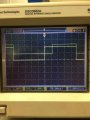
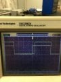
The Function Generator has two connections,I am going to order the parts in your circuit and hopefully it will work.
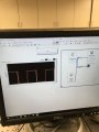
However I have another simple question. In your drawing you connected the negative side of the 5 v DC supply to the function generator. Do I have to actually do this? I think it only shows that all the grounds are connected to each other? Am I right or I really need to do this? If yes, to which part of function generator should be connected?
Thanks
- ground (connecting to any ground point and the author selected the (-) of the 5v supply),
- signal (out to the BNC TEE connector)