Syncing a camera and a pulsed flash light using a TTL signal

Thread Starter

Biofluid Lab Biofluid Lab

Joined Feb 17, 2017
24
I am not an electrical/electronic engineer, so please bear with me as it might be pretty simple for you.

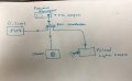
I have a monochromatic camera (www.qimaging.com/resources/pdfs/QICAM-12bitManual.pdf) which can be triggered (i.e. capture image) by a 5v TTL signal provided by an external triggering system (a function generator in my case: http://www.ms.sapientia.ro/elektronika/fileok/muszerek/cfg253_jelgenerator_leirasa.pdf).

So, basically I want to feed the camera a 5v TTL signal and make the camera capture an image (i.e. trigger) on the rising edge of the signal (High edge). I also have an external pulsed light source, supplying the required light for the image, which also needs to be synced with the triggering TTL signal on edge high mode (www.hsps.com/2006/pages/nanodren.htm).

I have come across a two issues for which I need help from you:

1) I am using a function generator with an in-built TTL output (BNC connection). So, when I monitor the function generator output, which is simultaneously connected to O-scope, camera and light source, the voltage amplitude is not 5v, but around 3v. That persists even if I set the function generator's impedance to High Z. I tried two different function generators and I get the same 3v. What's the reason behind this? How can I get an exact 5v TTL signal? I want my signal to be at least 5v as my external light source does not work consistently when the signal is below 4v. I already tried with 3v but the light source sometimes skip one pulse presumably because of the signal is insufficient. I heard somewhere that a pull-up resistor may solve my problem, but I have no idea about that.

Note: internal impedance of the function generator is 50 ohm.

2) Now the sync issue: the camera delay time is around 15 microsecond, meaning it takes for the camera 15 microseconds to open its shutter after receiving the high edge of TTL signal. On the other hand, the delay associated with the light source is around 2 microseconds. So, I won't get any image because the light has already been out when the camera shutter opens. So there is no light when the camera shutter is open. Therefore, basically I need to further delay the light source (say, 15 microseconds more, meaning a total of 17 microseconds) to be able to get image.

Thanks for taking time to read my post!
 

Attachments

AnalogKid

Joined Aug 1, 2013
10,987
As you've noticed, TTL and 5V are not the same thing. TTL is anything above 2.4 V. Still, the loading seems a bit high. Can you connect each of the devices singly and not the voltage sag for each? Also, why not use the main output from the signal generator? It has an adjustable amplitude that you can crank up until everyone sees it.

How accurate does the width of the 8 ns pulse need to be? AND, 8 ns seems awfully short for a light source. Not many photons, and not much time to integrate them. Do you have a circuit that makes the 8 ns pulse now?

There are two ways to delay the 8 ns pulse, with a true delay circuit that delays each edge by the same amount, or with two monostables in series, one for the delay time and one to make an output pulse. In this case, the output pulse width will not track changes in the input pulse width.

ak
 

Thread Starter

Biofluid Lab Biofluid Lab

Joined Feb 17, 2017
24
Thanks for your response.
Actually the manual and data sheet for both the camera and light source mentions that they require a TTL signal. I have already provided the links to their documents in the original post.
The input to light source says "TTL input". However, the documents and also the company representative told me that you must supply the light source with a TTL signal more than 4v!!

I already connected the two separately to see what happens. When nothing is connected to the function generator (except for the O-scope), I get a square wave of amplitude 4.2v (which is perfect).
When I connect the camera to the function generator (with O-scope still being connected), I get the same 4.2v.
But, when I connect the light source alone (again with O-scope being connected), the voltage drops to around 3.1v.
I know if the light source is activated by a TTL signal, it should still work with 3v. Actually, the flash light is triggered continuously with the existing TTL signal (3v); the reason I suspect it should not be enough is that sometimes I can hear that the light source skips one spark (especially at low frequencies like 1 Hz, it noticeable).

And yes, the flash duration is less than 10 ns (roughly around 8 ns). That's what I need because I am capturing fast moving particles under the microscope objective.


Thanks
 

EM Fields

Joined Jun 8, 2016
583
Thanks for your response.
Actually the manual and data sheet for both the camera and light source mentions that they require a TTL signal. I have already provided the links to their documents in the original post.
The input to light source says "TTL input". However, the documents and also the company representative told me that you must supply the light source with a TTL signal more than 4v!!

I already connected the two separately to see what happens. When nothing is connected to the function generator (except for the O-scope), I get a square wave of amplitude 4.2v (which is perfect).
When I connect the camera to the function generator (with O-scope still being connected), I get the same 4.2v.
But, when I connect the light source alone (again with O-scope being connected), the voltage drops to around 3.1v.
I know if the light source is activated by a TTL signal, it should still work with 3v. Actually, the flash light is triggered continuously with the existing TTL signal (3v); the reason I suspect it should not be enough is that sometimes I can hear that the light source skips one spark (especially at low frequencies like 1 Hz, it noticeable).

And yes, the flash duration is less than 10 ns (roughly around 8 ns). That's what I need because I am capturing fast moving particles under the microscope objective.


Thanks
The reason you're only getting 3.1 volts into the sparker is because it has a low impedance input.
If you look at the circuit comprising the function generator and the sparker input, it'll look like this:

sPARKER.png
With the sparker needing at least 4 volts in to generate an adequate output, you'll need a way to feed the sparker the voltage it needs at the current it demands, and this seems to do it nicely:

Spark illuminator delay.png

I've also included the LTspice .asc file so you can play with the circuit if you want to.
Note, however, that R5 is part of the sparker.

Do you need a circuit description?
 

Attachments

Last edited:

Thread Starter

Biofluid Lab Biofluid Lab

Joined Feb 17, 2017
24
Hey there!
I am really grateful for your response.
Yes, actually I do need a legend or more explanation on different parts of the circuit, if possible.
In your image (named: spark-illuminator-delay-png), I am assuming V1 is the one coming from the function generator, right? So, what is V2? Is it another square wave or just a constant 5v DC?

I believe a circuit description might really help me.

Regards,
 

EM Fields

Joined Jun 8, 2016
583
Hey there!
I am really grateful for your response.
Yes, actually I do need a legend or more explanation on different parts of the circuit, if possible.
In your image (named: spark-illuminator-delay-png), I am assuming V1 is the one coming from the function generator, right? So, what is V2? Is it another square wave or just a constant 5v DC?

I believe a circuit description might really help me.

Regards,
OK, then.

V1 is the 5 volt supply for the opamp, the reference divider R2R3, and the opamp's output, and V2 is the output of the function generator.

R2 and R3 comprise a voltage divider, and their junction supplies Vcc /2 to the inverting input of U1, an opamp configured as a voltage comparator with hysteresis.

When V2 goes low, the camera's input will be pulled low and C1's charge will be quickly drained to near zero volts through R1 and D1, forcing the output of U1 (the input to the sparker) low.

When V2 goes high, however, the camera's shutter will open quickly, but the sparker's output will be delayed by the time it takes C1 to charge to the voltage on U1-, about 25 milliseconds.
 
Last edited:

Thread Starter

Biofluid Lab Biofluid Lab

Joined Feb 17, 2017
24
Ok, thanks a lot!!

Here are a few more questions:

1) What is that triangle with its apex pointing downward (just below the V1)? Is it ground (I don't think so)??

2) If V2 is my square signal coming from function generator, I don't know how to get its negative side connected to a common point with V1, C1, R3 and R5 and U1? I mean I ma getting my signal from function generator through a BNC cable, so how to set up that common point in your drawing (bottom most horizontal line)?

3) What if I want to increase/decrease the delay time for the spark generator? Should I play with the capacitor?

4) Is R5=141 ohm?

Sorry if my questions are too goofy? :)

Regards
 
Last edited:

djsfantasi

Joined Apr 11, 2010
9,156
The downward facing triangle is common or also known as ground.

As far as how to connect the circuit ground to the BNC cable, what are you using to connect the BNC now? I would expect some sort of connector on your PCB. In that case, the datasheet will identify the common connection. It's usually the external metal case on the cable termination.
 

EM Fields

Joined Jun 8, 2016
583
Ok, thanks a lot!!

Here are a few more questions:

1) What is that triangle with its apex pointing downward (just below the V1)? Is it ground (I don't think so)??

2) If V2 is my square signal coming from function generator, I don't know how to get its negative side connected to a common point with V1, C1, R3 and R5 and U1? I mean I ma getting my signal from function generator through a BNC cable, so how to set up that common point in your drawing (bottom most horizontal line)?

3) What if I want to increase/decrease the delay time for the spark generator? Should I play with the capacitor?

4) Is R5=141 ohm?

Sorry if my questions are too goofy? :)

Regards
There are no goofy questions. :)

1. It's Ground.

2. The shield of the cable is connected to ground, so as long as you connect everything up BNC wise, you'll always have a path to ground, like this:

Spark illuminator delay wiring.png

3. You could, but a better idea would be to make R1 a rheostat. See 2.

4. R5 is the input resistance of the sparker and isn't part of the delay circuitry proper. Sorry for the confusion.
 
Last edited:

Thread Starter

Biofluid Lab Biofluid Lab

Joined Feb 17, 2017
24
I don't know how to thank you enough for the time you spent replying to my concerns.
You saved me a lot of time.

Today I used a general purpose multi-meter to measure the input resistance of the spark generator. I don't know if I did it right or wrong. There is a BNC connection on the spark generator as the input for the TTL signal. So I simply connected one lead of the multi-meter to the outer edge of the BNC connection and the other lead to the central core and I got 1k ohm.
Does that make any changes to the delay circuit?

Also, I also would like to try to work around this issue using LabVIEW. I think the lab I am working in already has the required NI equipment to do that. Anybody know how I can do this using LabView.

Best,
 

GopherT

Joined Nov 23, 2012
8,009
I don't know how to thank you enough for the time you spent replying to my concerns.
You saved me a lot of time.

Today I used a general purpose multi-meter to measure the input resistance of the spark generator. I don't know if I did it right or wrong. There is a BNC connection on the spark generator as the input for the TTL signal. So I simply connected one lead of the multi-meter to the outer edge of the BNC connection and the other lead to the central core and I got 1k ohm.
Does that make any changes to the delay circuit?

Also, I also would like to try to work around this issue using LabVIEW. I think the lab I am working in already has the required NI equipment to do that. Anybody know how I can do this using LabView.

Best,

It depends on which bits and pieces of NI hardware you have. USB Adapters with analog/digital inputs laying around?
 

Thread Starter

Biofluid Lab Biofluid Lab

Joined Feb 17, 2017
24
Ok;
I have a 6052E 16 inputs, 16 bits I/O board installed on my computer.
Then, I have a chassis model NI SCXI-1000 along with four separate modules (which I don't know their use). See attached for the picure of chassis and four modules.
I also have labview 2010 installed on my computer.

Let me know if I can actually the do the same thing with Labview or not.

Thanks
 

Attachments

GopherT

Joined Nov 23, 2012
8,009
Ok;
I have a 6052E 16 inputs, 16 bits I/O board installed on my computer.
Then, I have a chassis model NI SCXI-1000 along with four separate modules (which I don't know their use). See attached for the picure of chassis and four modules.
I also have labview 2010 installed on my computer.

Let me know if I can actually the do the same thing with Labview or not.

Thanks
You should be able to plug your function generator into the NI SCXI-1600 segment of your SCXI frame.
Each pulse you can start a delay clock (in LabView).
Fire the Camera (nothing happens immediately because the camera is slow)
Start a second delay clock (12 mSeconds).
Fire the nanoSecond Light source (using Solid State Relay board (SCXI-1163) (note below)

You'll have to wait for your camera to save the picture so add another delay before repeating above.

Also, you may be able to eliminate the function generator - that pulse can be programmed in LabView

Finally, the relay is just a switch (There are 32 separate relays (pairs of pins) on that board). Select one pair and add a 5V supply to one pin, a 220 ohm resistor to ground on the other pin. Connect your flash trigger to the relay pin with the resistor. That pin will be pulled to ground until the relay connects. Then it will be instantly pulled to +5V when the relay connects.
 

Thread Starter

Biofluid Lab Biofluid Lab

Joined Feb 17, 2017
24
You should be able to plug your function generator into the NI SCXI-1600 segment of your SCXI frame.
Each pulse you can start a delay clock (in LabView).
Fire the Camera (nothing happens immediately because the camera is slow)
Start a second delay clock (12 mSeconds).
Fire the nanoSecond Light source (using Solid State Relay board (SCXI-1163) (note below)

You'll have to wait for your camera to save the picture so add another delay before repeating above.

Also, you may be able to eliminate the function generator - that pulse can be programmed in LabView

Finally, the relay is just a switch (There are 32 separate relays (pairs of pins) on that board). Select one pair and add a 5V supply to one pin, a 220 ohm resistor to ground on the other pin. Connect your flash trigger to the relay pin with the resistor. That pin will be pulled to ground until the relay connects. Then it will be instantly pulled to +5V when the relay connects.
Thanks for the reply.
But since I have not worked with Labview and NI instrument at all, I wish u could explain it in simpler form.
 

Thread Starter

Biofluid Lab Biofluid Lab

Joined Feb 17, 2017
24
There are no goofy questions. :)

1. It's Ground.

2. The shield of the cable is connected to ground, so as long as you connect everything up BNC wise, you'll always have a path to ground, like this:

View attachment 121004

3. You could, but a better idea would be to make R1 a rheostat. See 2.

4. R5 is the input resistance of the sparker and isn't part of the delay circuitry proper. Sorry for the confusion.
I am going to order the parts in your circuit and hopefully it will work.
However I have another simple question. In your drawing you connected the negative side of the 5 v DC supply to the function generator. Do I have to actually do this? I think it only shows that all the grounds are connected to each other? Am I right or I really need to do this? If yes, to which part of function generator should be connected?

Thanks
 
Last edited:
Top