Synchronous boost converter

Thread Starter

sinatra39

Joined Oct 18, 2018
15
Hello folks,

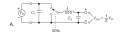
I have a problem understanding the attached circuit, a DC-DC voltage converter.
It says in the book where its depicted that "the average voltage across an inductor has to be zero, otherwise the magnitude of its overall current is rising without limits. From this it follows that the average output voltage is half the input voltage." (The switching ratio is 50-50)
What I dont understand now is the role of the inductor. Why do we need it in the circuit? Cant we just switch 50-50 without the inductor and also get a "time-average" voltage of half the input voltage?
And what would happen if we, say, attach a bulb between ground and the output voltage? Then this would mean that because through the inductor flows no current on average the bulb discharges the capacitor C2 and will never be recharged since the average current through the inductor is 0 and the circuit would only be useful for digital applications.
 

Attachments

crutschow

Joined Mar 14, 2008
34,285
What I dont understand now is the role of the inductor. Why do we need it in the circuit?
To store energy from the switched input and transfer it to the output with good efficiency.
Without the inductor to average the voltage, it will be averaged by the resistance in the circuit (from the switch and other strays) which will give no better efficiency than a linear regulator.
this would mean that because through the inductor flows no current on average
Why do you say that?
You appear to be confusing average voltage with average current.
The average steady-state voltage across the inductor is zero, but the average current is whatever the output load requires.
 

AnalogKid

Joined Aug 1, 2013
10,990
Cant we just switch 50-50 without the inductor and also get a "time-average" voltage of half the input voltage?
Yes, but ...
As above, that is a very inefficient way of dropping the input voltage. Also, the effective output impedance is higher so the output regulation is very poor. Also, the energy flow to the output is not continuous.

ak
 

ebp

Joined Feb 8, 2018
2,332
Welcome to AAC1

If the load on the circuit were a pure resistance, then the average output voltage would be the product of the duty cycle and the input voltage, but the current though the load would be pulsing instead of continuous and smooth. For things like incandescent light bulbs and heaters, that is generally OK, though both of those things respond to the RMS value of the waveform, not the average.

A problem arises as soon as we introduce a capacitor in an attempt to smooth the output voltage to make it continuous instead of pulsing. You cannot instantaneously change the voltage on a capacitor. Imagine the circuit with the inductor replaced by a short circuit, the switch in the down position to start and the capacitor discharged. The instant the switch was closed the current would rise, with perfect components with no resistance, to infinity. With real components, it would rise to some value limited by the "parasitic" resistance throughout the circuit. The current would drop in exponential fashion as the capacitor charged, but that first ultra-high peak value can't be tolerated with real parts. We could limit the current by using a resistor in series with the switch, but the resistor wastes energy as heat - we can't recover that energy in any practical simple way.

The current through an inductor, on the other hand, cannot be changed instantaneously. If we start the same way as before but with the inductor in the circuit, things behave a lot better. Before the switch is closed, the current through everything is zero. At the instant the switch is closed, the inductor current is still going to be zero. It will rise "slowly". Two important things happen while the switch is closed - the voltage on the capacitor begins to rise and energy is stored as a magnetic field "in" the inductor. If the switch is now set to the down position, the inductor "tries" to keep the current the same as it was before - same direction and same magnitude. Now the energy that was stored in the inductor is transferred to the capacitor and the load. If we repeat this sequence at high frequency, after several cycles the capacitor will charge up to the average voltage (input voltage times duty cycle). Assuming the load resistance isn't limiting (too high), the current in the inductor won't drop all the way to zero each time the switch is in the down position and the voltage on the capacitor will only change a little bit, so it looks like smooth DC. Ignoring losses due to circuit resistance, with 50% duty cycle the output voltage will be exactly half of the input voltage and the input current will be exactly half of the load current once everything has reached equilibrium. Generally for simple analysis of the converter it is assumed that the change in voltage on the capacitor during a single switching cycle is very small - typically tens of millivolts for a real circuit - even though we are adding charge for part of the time and removing it for part of the time (the small ripple voltage isn't just an assumption, in real circuits the capacitor value is chosen to be certain the ripple voltage is small). The peak to peak "ripple current" through the inductor in a practical circuit is often in the range of 20 to 40% of the average output current (again, something set deliberately by design). In equilibrium, the average voltage on capacitor is exactly equal to the average output voltage and the average current through it is zero, while the average inductor current is exactly equal to the average output current and the average voltage across it is zero, assuming the components are perfect and have no resistance.

The circuit you have shown is actually a buck converter - the output voltage is less than or equal to the input voltage. The voltage that appears across the inductor when the switch is ON acts in opposition to ("bucks") the input voltage. When the switch is in the UP position, there is direct current flow from the input to the output, through the inductor.

So, important things:
  • you cannot instantaneously change the voltage on a capacitor
  • you cannot instantaneously change the current through an inductor
  • both the capacitor and inductor store energy during part of the switching cycle and deliver energy during another part
 
Top