Switching polarity of a DCC signal (model railway control)

Thread Starter

AlbertHall

Joined Jun 4, 2014
12,660
ould you use a photo sensor to detect when a train enters the loop to reverse the phase of the isolated track, and then another sensor to go back the the normal phase when it is completely in the isolated track?
Since it now doesn't have to switch rapidly to remove a short current, the photo sensors could control a DPDT reversing mechanical relay.
I have found a description of just that idea:
 

Thread Starter

AlbertHall

Joined Jun 4, 2014
12,660
It would have to work in either direction. Note that a reversing section may have multiple entrances and exits. If the TS has a simple reversing loop, this is a viable option. However, the logic for all cases could get quite complex and would have to be created individually for all arrangements of reversing sections. This is one reason why the commercial modules look for a short. (Plus on a model railroad, a photo sensor is not prototypical and clever scenery design would be needed to hide it.)
See post #21.
The eventual intention is that it will all run itself under computer control. You just have to set up a schedule and away it goes.
 

crutschow

Joined Mar 14, 2008
38,913
I have found a description of just that idea:
So my idea is not totally off-the-wall.

He uses an Arduino for the logic, but I think it could also be done with some reasonably simple discrete logic (although I haven't worked it out) if you want to avoid using and programming a micro.

I also saw a video where they mentioned using magnetic detectors, so that's an option also.
 

crutschow

Joined Mar 14, 2008
38,913
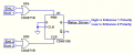
Here's my thought on the logic required:

You have two sensors --
  • One to detect the train just before it enters the loop
  • One to detect the train just before leaving the loop.
The logic is--
  • The first sensor switches the relay loop polarity to be the same as the entrance track.
  • The second sensor reverses the polarity to be the same as the exit track.
This could be done with some interface circuitry to the sensors, and an RS latch controlling the relay.

If the circuit has to sense trains from either directions, then that would require two entrance sensors and and two loop sensors.

Below is the logic for trains from either direction with 4 sensors:
For just one direction and two sensors, the OR gates are not needed

1714519721258.png

Does that sound feasible, or did I miss something?
The logic is pretty simple, so don't know why the guy on the YouTube video used an Arduino.
 
Last edited:

djsfantasi

Joined Apr 11, 2010
9,237
First, I want to say that the ideas presented are good ones. My comments are not meant to denigrate anyone’s contribution. I just want to present possible additional details to the problem.

Okay, but won't it work to have the sensors just before and after the isolated track section?
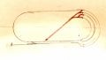
If you mean at each boundary, entrance or exit, to the reversing section, then I’ll agree. The track topology may have four entrances at one end and a single entrance on the other end, thus requiring five circuits to control one relay.

Here is an example layout. The reversing section is marked in red. There are five entrances. IMG_8801.jpeg

Is that a big problem?
The sensor could possibly be built below the track, looking up.
Depending on the requirements of the user, it could be a big problem. Those striving for a realistic layout, the gaping hole without track ballast for a sensor under the tracks could be a problem.

Just thought it might be a cheaper way to perform the function, which the TS was looking for.
Again, it could very well be. As I said, depending on the realism level as a goal and a simple track topology and a simple set of logic, it’s a great solution.
 

crutschow

Joined Mar 14, 2008
38,913
The reversing section is marked in red. There are five entrances.
Why couldn't you put the track block for the reversing section and single sensor after all the entrances join?
Those striving for a realistic layout, the gaping hole without track ballast for a sensor under the tracks could be a problem.
I don't think it requires a "gaping hole" for a miniature reed relay.
I assume they already use track sensors for things like operating a crossing arm or light, so why would it be different from what they use for that?

You seem to be trying very hard to magnify any negative issues you can find about my approach. :rolleyes:
 
Last edited:

djsfantasi

Joined Apr 11, 2010
9,237
I don't think it requires a "gaping hole" for a miniature reed relay.
I assume they already use track sensors for things like operating a crossing arm or light, so why would it be different from what they use for that?
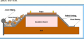
Model railroaders “ballast” their track. Ballasting consists of using a sand-like (or smaller) brushed between the rails and ties forming a contoured edge. IMG_8803.pngMy use of “gaping” was hyperbolic. But any interruption in this sub-surface would be noticeable

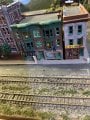
Here is the track on my model railroad:IMG_8802.jpeg
Maybe you can see what I mean.
 

djsfantasi

Joined Apr 11, 2010
9,237
I can.
But don't you use any sensors for operating gate crossings, etc?
Yes, but they are all operated by sensing the current flowing between the two rails.

You seem to be trying very hard to magnify any negative issues you can find about my approach. :rolleyes:
I apologize that it seems that way. You are looking at it from an electronic viewpoint it appears. I just am approaching it from a modeling perspective.
 

djsfantasi

Joined Apr 11, 2010
9,237
How do they do that?
The track is divided into segments which are isolated by gapping one or both rails. The sensing modules/circuits are then placed in series between the power wire and the track. The track becomes a series of SPST switches where the train is the switch contact.
 

crutschow

Joined Mar 14, 2008
38,913
The track is divided into segments which are isolated by gapping one or both rails. The sensing modules/circuits are then placed in series between the power wire and the track. The track becomes a series of SPST switches where the train is the switch contact.
So it would seem, that also could be used for sensors in the reversing loop.
 
Last edited:

djsfantasi

Joined Apr 11, 2010
9,237
So it would seem, that also could be used for sensors in the reversing loop.
Yes! It could… but consider with the added complexity and cost, the commercial reversing module is more and more attractive. The TS rejected the idea because of the cost. This would be replacing one module with multiple modules plus glue logic and a reversing relay. Plus you’d have to determine the track switches (aka turnout) position and use that in your logic as well. (Which polarity do you want to match? The normal or reverse leg of the turnout?)

The commercial module is just plug&play in most situations.
 

Thread Starter

AlbertHall

Joined Jun 4, 2014
12,660
In what way is it a "little more complicated"?
How does my logic not work?
You have a loop with track breaks near the ends and the two sensors just outside the breaks.
A train comes along past one of the sensors and the circuit sets the loop power for that train. The train crosses the first break and all is well. But when it gets to the second break the rails have the opposite polarity so a short will occur when the wheel bridge the gap.

You have to wait until the whole train has passed the first track break and then reverse the polarity so it will be correct at the second break.
 

crutschow

Joined Mar 14, 2008
38,913
This would be replacing one module with multiple modules plus glue logic and a reversing relay.
Why do you think it requires multiple modules?
It's one circuit consisting of the sensor interfaces (not needed for a reed switch magnetic sensor), plus a FF IC, and an OR gate IC if you need both directions.
Very simple.
Plus you’d have to determine the track switches (aka turnout) position and use that in your logic as well. (Which polarity do you want to match? The normal or reverse leg of the turnout?)
Sorry, but once again you seem to be trying to confuse things by bringing up straw-man problems.

The logic is simple--
There is one sensor near the loop entrance, after any multiple loop inputs, to switch the loop polarity to match the entrance track polarity, and one sensor near the loop exit, (before any multiple loop exits) to switch the loop polarity to match the exit track polarity.
That's the polarity I match.

The NC relay contacts are connected to the entrance track and the NO contacts are connected to the exit track, with the wiper contacts connected to the loop track.
So the entrance sensor turns off the relay, and the exit sensor turns on the relay.

What about that is confusing?
 
Last edited:

crutschow

Joined Mar 14, 2008
38,913
You have a loop with track breaks near the ends and the two sensors just outside the breaks.

A train comes along past one of the sensors and the circuit sets the loop power for that train. The train crosses the first break and all is well. But when it gets to the second break the rails have the opposite polarity so a short will occur when the wheel bridge the gap.
No.
I thought what I said was clear in post #24:

The logic is--
  • The first sensor switches the relay loop polarity to be the same as the entrance track.
  • The second sensor reverses the polarity to be the same as the exit track.
The second sensor is placed inside the loop near the end, so the train is completely in the loop, where it then sets the polarity to be the same as the exit track before it exits the loop.

Make sense now?

Perhaps it's my imagination but it seems everyone (including the YouTube guy) is trying to over-complicate what is required to perform a simple task.
 
Last edited:

djsfantasi

Joined Apr 11, 2010
9,237
I’m done after this.

Sorry, but once again you seem to be trying to confuse things by bringing up straw-man problems.
Perhaps it's my imagination but it seems everyone (including the YouTube guy) is trying to over-complicate what is required to perform a simple task.
I’ve tried explaining why it’s not as simple as you seem to think it is but get accused of bringing up straw man arguments.

The first published model railroad track sensor was in the 1950s. Decades of experience from thousands of modelers, a good portion who are electronic engineers, have been working to develop an inexpensive reliable sensor.

One track sensor is available commercially for $15-$20. You’d need at least two. The commercial module costs $30 and the TS rejected it as being too costly.

I’m done.
 

Thread Starter

AlbertHall

Joined Jun 4, 2014
12,660
The second sensor is placed inside the loop near the end, so the train is completely in the loop, where it then sets the polarity to be the same as the exit track before it exits the loop.
Except that assumes the trains will only go one direction round the loop, but they need to be able to move both ways.
 
Top