 Facebook
 Google
 GitHub
 Linkedin
Hi,
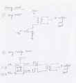
I need to switch 30V from a transformer primary to secondary, switching is done by providing a PWM/pulse input so when the input is high, differential voltage at secondary is 30V or Vcc and when input is low, differential voltage at secondary is zero. I'm using a 1:1 transformer. As the output needs to be 24V, 100mA minimum, I am providing upto 30V to the primary to take care of the diode drops in the bridge rectifier and the minimum requirement for a regulator (will be added after rectifier stage). The attached picture 1 shows this.
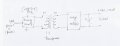
1. The first approach(1. in picture 2) I have taken is to use mosfet (n channel) like IRFZ44 to switch the 30V supply to the primary at a rate of 10KHz. The problem was the secondary side shows low duty cycle output. Could anyone explain me this and kindly suggest me how to proceed with this approach.
2. Another approach(2. in picture 2) I have in mind is to use a H bridge IC like L293D or L298 and use two outputs to supply to the transformer primary. I need to know if I missed something here or this approach will do fine.
My concerns:
1. In both approaches, I'm not sure how to control the drain current through the MOSFET. The datasheets say, for Vgs = 10V, Id = 1A (lets say) and also Vgs threshold is 2V-4V. What does this mean? If I provide Vgs= 10V, how do I make sure Id is limited while the drop at transformer primary is also maintained at Vcc?
2. If I switch at a frequency higher than 10KHz, what other factors do I need to consider here?
(I know I should ask this if one of the above approaches are working fine for me but still I'm curious)
(please do let me know if I should provide any other details)
Thanks for your time,
Zaman
I need to switch 30V from a transformer primary to secondary, switching is done by providing a PWM/pulse input so when the input is high, differential voltage at secondary is 30V or Vcc and when input is low, differential voltage at secondary is zero. I'm using a 1:1 transformer. As the output needs to be 24V, 100mA minimum, I am providing upto 30V to the primary to take care of the diode drops in the bridge rectifier and the minimum requirement for a regulator (will be added after rectifier stage). The attached picture 1 shows this.
1. The first approach(1. in picture 2) I have taken is to use mosfet (n channel) like IRFZ44 to switch the 30V supply to the primary at a rate of 10KHz. The problem was the secondary side shows low duty cycle output. Could anyone explain me this and kindly suggest me how to proceed with this approach.
2. Another approach(2. in picture 2) I have in mind is to use a H bridge IC like L293D or L298 and use two outputs to supply to the transformer primary. I need to know if I missed something here or this approach will do fine.
My concerns:
1. In both approaches, I'm not sure how to control the drain current through the MOSFET. The datasheets say, for Vgs = 10V, Id = 1A (lets say) and also Vgs threshold is 2V-4V. What does this mean? If I provide Vgs= 10V, how do I make sure Id is limited while the drop at transformer primary is also maintained at Vcc?
2. If I switch at a frequency higher than 10KHz, what other factors do I need to consider here?
(I know I should ask this if one of the above approaches are working fine for me but still I'm curious)
(please do let me know if I should provide any other details)
Thanks for your time,
Zaman
Attachments
-
 74.3 KB Views: 41
 -
 52.7 KB Views: 39


