Switching Circuit Help for 20 Resistors & 19 Dc Fans

MMcLaren

Joined Feb 14, 2010
861
Are you referring to the CA-42 cable? If so, that may not be the best choice for you. I've got a couple CA-42 cables on order from China (less then $3 each) but I intend to cut that Nokia OEM connector off and install a 6-pin IDC connecter to match the pinout of the FTDI FT232R cable connector.

Regards, Mike
 

Thread Starter

kiranp

Joined Mar 13, 2010
9
Yes the CA-42 cable, Im thinking of chopping of the end too and using a 4way header/plug connection.
The problem is i dont know which or how many of the wires that are included with the CA42 must be connected to the pins of the PIC10f200 chip.

I see in the K8LH diagram that there is a GND and One other connection from the cable to GP1, which of the wires is used? Is there really only 1 connection being used from the cable to drive the PIC?
 

Thread Starter

kiranp

Joined Mar 13, 2010
9
SGTWOOKIE:
Have ordered the MIC's from farnell, are you sure i need just 3? MmcLauren mentioned that i need 5; i have in total 39 channels.

To be honest i was getting a bit lost on the ratings etc., but seeing it all calculated makes it easier! Much thanks for that and for the pin 10 hint!

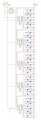
I have dabbled in multisim to design the circuit, (picture below-apologies if its huge).
I have added decoupling capacitors to reduce noise.

Problems:
1. Are the pin configurations correct?
2. Unsure on which connections to use from the USB - serial Cable (CA-42)
3. Do i leave serial out pin on the last MIC?

Please make any comments about the design, whether I’ve made incorrect, missing or totally useless connections! I will attach the multisim file too.

Having a go at creating the PCB now.
 

Attachments

SgtWookie

Joined Jul 17, 2007
22,230
If you control a single resistor and fan with one output, you will need three per system.

You will need at least 5 per system if you wish to control the fans and resistors separately.

If you want completely independent control of the fans and resistors for PWM purposes, you will need six per system; three for the fans, three for the resistors.

An alternative might be to use a single MIC5841 output to switch the grounds of a resistor and a fan, and then use a single P-ch MOSFET for PWM control of the fan +12v supply. This would help keep costs and board size down. You would then need three MIC5841's and one P-ch MOSFET with a suitable driver circuit.
 
Top