Switching a 24VAC solenoid, TRIAC, Relay or SSR?

AnalogKid

Joined Aug 1, 2013
12,238
Thanks - I got caught up on your reference to -5V, I don't understand why its a negative voltage.
"
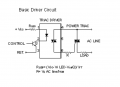
Because triacs require substantially greater gate current for Quadrant 4 operation it is best to operate a triac only in Quadrants 1, 2, and 3. This can easily be achieved by making the positive side of the DC supply the common leg for DC and AC supplies and tying MT1 to it. The net effect is that triac gate will be sinking current to trigger the triac instead of sourcing it—the reverse of the preceding circuits. This means that the triac will be operating in Quadrants 2 and 3. The circuits below illustrate how this can be achieved using transistors.
"
https://apollo.neocities.org/electromotiveforces/triac.html

ak
 

BobaMosfet

Joined Jul 1, 2009
2,211
We’re dealing with an AC supply here, switched with triacs!
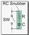
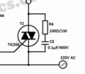
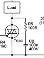
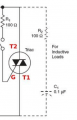
A snubber is a resistor and capacitor in series, connected either across the triac, or across the load: what you described is a flywheel or fly back diode.
However, as virtually every triac you are likely to find is rated at >400V, the chances of a voltage spike big enough to damage it from a 24V AC supply are pretty slim.
I stand corrected- thank you very much! I had only heard flyback/snubber used interchangeably, and knowing the difference, particularly as regards AC is very helpful. Again, thank you for the clarification.
 

Ian0

Joined Aug 7, 2020
13,227
I stand corrected- thank you very much! I had only heard flyback/snubber used interchangeably, and knowing the difference, particularly as regards AC is very helpful. Again, thank you for the clarification.
On a DC system, flyback diode and snubber can be used interchangeably!
 

Thread Starter

ilium007

Joined Aug 24, 2013
139
I have spent weeks in my down time reading about TRIAC control. I am still pretty confused as to how I get a negative 5v current to switch a triac in Q3. This aside, if I were to use a TRIAC output photocoupler such as a MOC3060 to switch a bigger triac, how does the photocoupler switch in the correct quadrants? Does it work because the photocoupler MT2 terminal is connected to the same MT2 terminal of the switched TRIAC? So whenevener the AC active is +ve the gate on the Power TRIAC will be positive, when AC active is -ve the gate on the Power TRIAC will be negative also.

1610320276444.png
 

sghioto

Joined Dec 31, 2017
8,737
The way I understand this is if the cycle is in the 4 quadrant when the opto control is activated the zero crossing detector won't trigger the internal triac until the
start of quadrant 1.
 

Ian0

Joined Aug 7, 2020
13,227
The opto-triac triggers the triac in quadrants 1 and 3. It can only trigger it in quadrants where the gate is the SAME polarity as MT2, because it derives the gate current from the same place as MT2. Whether it has a zero crossing detector or not is completely irrelevant. Opto-triacs WITHOUT zero-crossing detectors will also always trigger in 1 and 3.
so when you say
Does it work because the photocoupler MT2 terminal is connected to the same MT2 terminal of the switched TRIAC? So whenevener the AC active is +ve the gate on the Power TRIAC will be positive, when AC active is -ve the gate on the Power TRIAC will be negative also.
you are absolutely correct.


I am still pretty confused as to how I get a negative 5v current to switch a triac in Q3
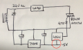
Refer to my circuit in post #18
When triggering the triac from an external -5V supply, it operates in quadrants 2 and 3.

The only way to achieve quadrant 4 triggering is from an external supply which is positive with respect to MT1.
 
Last edited:
Careful, zero-crossing optocouplers can have a high inhibit voltage: MOC3061 12-15V, MOC3031 20V which makes them unsuitable for 24VAC. They're really designed for mains applications.
 

Ian0

Joined Aug 7, 2020
13,227
Careful, zero-crossing optocouplers can have a high inhibit voltage: MOC3061 12-15V, MOC3031 20V which makes them unsuitable for 24VAC. They're really designed for mains applications.
A high inhibit voltage on 24V AC, will mean that they will still work, but may be a long way from zero-crossing when they trigger, in other words - no point in using the zero-crossing type, as the effect will me much the same as using a non-zero-crossing type.
A zero-crossing type has very little advantage in switching an inductive load on a low AC voltage.
(The ideal time to switch a very inductive load is at mains peak, not zero crossing. This mainly applies to transformers as they will always saturate at the end of the first cycle if switched at zero-crossing. Not so much of a problem with solenoids.)

The main problem with using an opto-triac on low voltage is the voltage drop - the main triac will not trigger until the current through the series resistor (180 ohms in this case) is greater than the trigger current plus the bleed current. (4.5mA) - a total of 12mA. That is 2V across the opto-triac plus 2.2V across the resistor plus 1.5V across the gate-MT1 junction of the main triac. So it doesn't trigger until the AC voltage has reached 4V - and that's at 25 degrees C. Trigger current is higher if it's cold.

The trigger current is only specified at 12V on MT2. It is not specified at all for lower voltages.

For low-voltage AC operation the -5V DC supply for triggering is a much better option
 

Ian0

Joined Aug 7, 2020
13,227
The net effect is that triac gate will be sinking current to trigger the triac instead of sourcing it—the reverse of the preceding circuits. This means that the triac will be operating in Quadrants 2 and 3.
Not the reverse of the preceding circuits at all - EXACTLY as shown in post 18.
 

Thread Starter

ilium007

Joined Aug 24, 2013
139
Not the reverse of the preceding circuits at all - EXACTLY as shown in post 18.
I will go back to the circuit in post 18, I still don't really understand how you have negative voltages, I have never played with dual rail power supplies or dual op amps so I guess I don't really understand the concept. Still, in the circuit diagram in post 18 how would negative voltage be switched with an MCU? How is a negative voltage trigerred? In my case I will still need a switching power supply to get 24VAC down to a managable level to feed into the 7905 (peak 24VAC will be about 34V), the logic side of the circuit will be 3.3V.

1610883884467.png
 
Top