 Facebook
 Google
 GitHub
 Linkedin
Hi,
I don't have much experience with electrical circuits, but now I'm facing an issue that google was not able to help (or me not able to understant) so I hope someone could at least point me in the right direction.
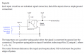
I have circuit that in order to be activated I only have close the circuit image in attachment (Router circuit.png).
The circuit responsable to activate/deativate this switch delivers 5v when it should open the router switch and 0v when it should activate/close router switch the circuit.
I have investigated the opto-coupler in order to isolate both circuits but I was unable to find one that closes the curcuit when the input is 0v and opens when 5v is present. I don't know if I'm even on the right path.
Hope this was clear, and I'm sorry if it wasen't more descritive or into details, but I can try to give more details if needed.
Any help is welcome.
Thanks in advance,
Ricardo Rio.
I don't have much experience with electrical circuits, but now I'm facing an issue that google was not able to help (or me not able to understant) so I hope someone could at least point me in the right direction.
I have circuit that in order to be activated I only have close the circuit image in attachment (Router circuit.png).
The circuit responsable to activate/deativate this switch delivers 5v when it should open the router switch and 0v when it should activate/close router switch the circuit.
I have investigated the opto-coupler in order to isolate both circuits but I was unable to find one that closes the curcuit when the input is 0v and opens when 5v is present. I don't know if I'm even on the right path.
Hope this was clear, and I'm sorry if it wasen't more descritive or into details, but I can try to give more details if needed.
Any help is welcome.
Thanks in advance,
Ricardo Rio.
Attachments
-
 115.7 KB Views: 32


