With one source and the 10 Ohm resistor you don't need the superposition theorem. Do you mean, an example where you have two sources connected to the 10 Ohm resistor? Maybe you could provide a drawing of what you are interested in.
So read the following text from the AAC book and show us your best attempt at a solution. That will be the basis for guiding you to a complete understanding of the subject.
If you replace the voltage sources with arbitrary voltage sources (V1 and V2, for instance), then you will find that any of the voltages and currents in the circuit, if it is a linear circuit, will be of the form of a linear function of two variables:
Vx(V1,V2) = K1·V1 + K2·V2
or
Ix(V2,V2) = V1/R1 + V2/R2
Where K1, K2 and R1, R2 are coefficients that come out of the circuit analysis (in general they do NOT match particular values in the circuit, so if the circuit happens to have a resistor labeled R1, that is pure coincidence and is not the same as the R1 above -- use parameter names that don't collide with component designators in the circuit you are working with).
Give an equation of this form, we can break it up into:
Vx(V1, V2) = Vx(V1,0) + Vx(0,V2)
Vx(V1,0) is simply the original circuit with V2 set equal to 0V, which is the same as replacing it with a short circuit. So we can remove V2 from the circuit, replacing it with a short circuit, and then do the analysis of this new, simpler circuit and the value we get for Vx is Vx(V1,0). We do the same thing, only removing V1 and replacing it with a short circuit, to get Vx(0,V2). When we add the results, we have Vx(V1,V2) which is the value of Vx in the circuit when both sources are present.
Hi, I've read through the notes and have got to this part where they have all the numbers in the table, it doesn't show you how they've got theses numbers, can you help with this? Thanks
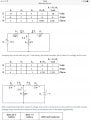
In the first diagram look at the row labeled R. You will agree that the values listed for R1, R2, And R3 are correct by inspection of the diagram. The heading of the 4th column is labeled
R2 || R3
That is a shorthand notation for R2 in parallel with R3. You know that this value must be:
Now you have a 28 V source in series with a 4 Ω resistor and a 0.667 Ω resistor (the parallel combination of 1 Ω and 2 Ω. By the relentless application of Ohm's law you KNOW that the current in the series circuit must be....what?
Add that to your table, and proceed with the remaining entries.
No. You might have missed Papabravo's post above. It is a shorthand indicating that the two components are in parallel, meaning that they have the same voltage and that the total current is the sum of the currents through each. Are you familiar with combining parallel resistors?
I am doing a HND in aeronautical engineering, it's s distance learning course and all the notes given are completely useless. I am a mechanical aircraft engineer so I don't deal with electrical circuits at all and while I did my trade training we spent a week at most on electrical circuits and this was maybe 5 years ago now!
I am doing a HND in aeronautical engineering, it's s distance learning course and all the notes given are completely useless. I am a mechanical aircraft engineer so I don't deal with electrical circuits at all and while I did my trade training we spent a week at most on electrical circuits and this was maybe 5 years ago now!
When you did your electrical circuits work in the past, did you use conventional current (i.e., the electrical current is the flow of electrical charge from positive to negative) or electron current (i.e., the electrical current is the flow of electrons from negative to positive)?
The reason for doing these things is to give you a breadth of experience so that your engineering education is not 1-dimensional. I had to take statics, dynamics, strength of materials, and fluid mechanics for my undergraduate degree in Electrical Engineering. After 50 years, I'm still working on the general solution to the Navier-Stokes equations in my spare time. Electrical circuits and heat transfer have a great deal in common for example.
The way you combine two resistors in parallel and express them as a single resistance Req is as follows:
It would be very unusual for you to go through a career as a mechanical engineer and not get involved with electrical systems from time to time. Even as a hydraulic systems technician I dealt with both electrical and mechanical systems on a routine basis.
The E-book here used electron current, which is a decision made by the forum founder. Most of the world, including most engineering programs, use conventional current (i.e., charge flow) and so it might be confusing to use the E-book and have to switch back and forth all the time.
I'd recommend getting a basic introductory EE Circuits textbook. You can find used ones very cheap on Amazon or similar. Start from the beginning and work your way through. Much of it you will probably be able to just read while laying in bed at night. Work through the examples if you have any doubts about your understanding of the material. Focus on understanding the concepts, not on memorizing equations or problem solving steps.
For example, for our resistors in parallel we want to find the value of a single resistor that would be equivalent. So what we are looking for is the following
where we want to find a value for R3 such that we would replace the two resistors R1 and R2 with R3 and have the same total current, Io, when the same voltage Vo, is applied as shown.
We know that in the left circuit that Io = I1 + I2 and that in the right circuit that Io = I3
We know, from Ohm's Law, that I1=Vo/R1, I2=Vo/R2, and I3=Vo/R3
Combining these, we get that
Vo/R3 = V0/R1 + Vo/R2
We can cancel Vo from both sides, leaving us with
1/R3 = 1/R1 + 1/R2
This is the basic relation for combining resistors in parallel and it holds for however many resistors you might have by just adding the reciprocal of the resistances to the the reciprocal of the equivalent resistance.
For just two resistors, you should be able to solve the equation above for R3 and get
Relax and take a deep breath. If you can design an inherently stable airframe then circuits should not cause you to panic. Take it one step and one question at a time.
Theses are the note I was given to complete this question.
Superposition Theorem In any network containing more than one voltage source, the current in, or potential difference developed across, any branch can be found by considering the effects of each source separately and adding their effects. During this process, any temporarily omitted source is replaced by its internal resistance (or a short-circuit if it is a perfect voltage source) Procedure – (example of a circuit with two sources of e.m.f. E1 and E2) 1. redraw the original circuit with source E2 removed. If there is an internal resistance associated with E2, this should be put in it’s place, otherwise assume a short circuit 2. label the currents in each branch, indicating their directions and determine their values. Nb. convention dictates that current flows from the +ve battery terminal 3. redraw the original circuit with source E1 removed, replacing that by it’s internal resistance if there is one, otherwise assume a short circuit 4. label the currents in each branch, indicating their directions and determine their values 5. superimpose the redrawn circuits on each other 6. determine the algebraic sum of the currents flowing in each branch As before, any negative signs indicate current direction are the reverse of original assumptions
Yep that pretty much sums up the technique. You were well on your way in the first example from the eBook where we considered the parallel combination of a 1 Ω and a 2 Ω resistor. In a previous post I showed you that it was 2/3 Ω or 0.667 Ω. Because we now can draw the first circuit as a 28 Volt Battery connected to a 4 Ω resistor and a 0.667 Ω resistor (the parallel combination of 1Ω and 2Ω), we know that whatever current flows must be equal in both resistors. We apply Ohm's law to compute this total current by dividing the voltage (28 V) by the total resistance (4.66...... Ω) and we get 6 Amperes.
Now we know that 6 Amperes of current is going through the 4 Ohm resistor, so the voltage drop across the resistor must be by a second application of Ohm's law: 6 Amperes time 4 Ω or 24 Volts. If the voltage across R1 is 24 Volts then the voltage at the junction of R2 and R3 must be equal to the battery voltage minus 24 or 4 Volts. If the voltage drop across R2 and R3 is fixed at 4 Volts then the current through R3, the 1 Ω resistor is 4 volts / 1 Ω = 4 amperes, and the current through R2 the 2 Ω resistor is 4 Volts / 2 Ω = 2 Amperes. And now you have the first table filled in.
There are three equivalent form of Ohm's law
E = I * R
I = E / R
R = E / I
Can you figure out the second circuit on your own now?
 Facebook
 Google
 GitHub
 Linkedin