ummm if perfboards are spaced 0.1" then it is the same problem than with breadboards, isnt it?
is this special spacing of this particular IC named something so that I can search in the web?
I ve seen this IC soldered to something. I have to figure it out to what
ummm if perfboards are spaced 0.1" then it is the same problem than with breadboards, isnt it?
is this special spacing of this particular IC named something so that I can search in the web?
I ve seen this IC soldered to something. I have to figure it out to what
0.1" is standard spacing for thru-hole components. Occasionally you'll find a device not designed for prototyping which has a strange pitch (pin spacing). For those you will need to do one of two things:
1) Build an adapter that accepts the strange pitch and spreads it to standard 0.1" spacing
2) Solder wires onto the pins of the device with a strange pitch and use those to plug in to the breadboard (or perf/strip board).
Make an adapter like the attached. I assumed row space on your device was 0.2". Find socket strips that will fit the pins on your device and install on the inner rows; standard female header strips may work, but you might need solder wipe strips or maybe machined pins. For outer rows use standard male header strips.
I have a very basic question. How do you connect general wires to a breadboard??
So far I have done it the brute force way, just try to insert it to the holes. Obviously this is not the prettiest thing so I would like to hear an expert opinion. Wires are not like jumper wires that enter neatly right ?
Kudos if the solution is simple and doesnt take so much of time or resources
Also how do you put the SLA7024M to a breadboard? the pins seem in a strange arrangement....
The pins on that chip could do with a bit of cleaning up - even if you manage to somehow wedge it into a breadboard, flux and oxides on the previously soldered pins with ruin the spring contacts in the breadboard.
The best tool IMO is a pair of smooth jaw pointy-nose pliers, first flatten all the pins, then draw the smooth jaws down each pin - it gets them just a little straigter and scrapes off any oxide/excess dolder.
Always use single core solid hookup wire, the thinnest that will make reliable contact so as to not stretch the spring leaves - some people twist and tin stranded hookup wire - *DONT* - tinning the wire leaves traces of flux, that transfers to the contact leaves and forms a hard insulating layer.
With all this concern of adapting the IC's pins to the breadboard spacing, you may forget that he should not use the breadboards contacts for the high (0.7A +) current. Like for the steppers power, drive, and sense lines.
With all this concern of adapting the IC's pins to the breadboard spacing, you may forget that he should not use the breadboards contacts for the high (0.7A +) current. Like for the steppers power, drive, and sense lines.
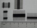
I drew it using Eagle. If I were to build one, I'd use pins something like the pins below for the chip and male headers for inserting into the breadboard.
The pins are shown with a 0.025" square header pin inserted. If the leads are smaller, you could use machined pins from an IC socket. You want male headers with long leads so you can insert through the top side and still have enough lead length to insert in the breadboard.
You could hand wire on perf board, but the non-standard lead pitch will be problematic. I'd make a PCB.
Although the pics are not clear I can see the SLA 7024M mounted on a perfboard
So I guess it is possible . Also I see something else near, is that a heatsink??
UPDATE: Went to the electronic store, and no it is not possible....tried several perfboards
Also in the post below I see that the IC is inserted in a breadboard. I don't know what is the voltage of the motor there but it is written that the current it uses is 1 A.
I use the "toner transfer" method, but I made my first boards decades ago using a black "Sharpie" marker. You also need copper clad board (preferably one sided, half ounce will etch faster), ferric chloride (or similar) to etch, a small drill press and a carbide drill bit. To cut the board, I use a shear; but you could use other methods.
Regarding the perf board photo... It looks like they bent the pins to fit the 0.1" grid.
One colleague show me a solution. To perforate holes in a "universal board" (that is what we call it here, no one knows what a perfboard is), make a huge rectangular hole in the boardwith a drill, insert the IC, and solder the pins to the nearest hole with metal. It seems simple for an expert but for my monkey hands, guess it will take some hours to do that... Hope dont break the IC
 Facebook
 Google
 GitHub
 Linkedin