Suggestions for very fast control of highly transient load

MisterBill2

Joined Jan 23, 2018
28,059
There does need to be some minimum load before the switches so that the supply is not going in to an unloaded mode, because that is very hard to keep a regulated voltage with no load. Perhaps 5% of the max output could be going into the minimum loading resistor. The exact amount will need some experimentation.
 

ronsimpson

Joined Oct 7, 2019
4,777
Looking at your schematic:
I do not understand the circles with V or A in them.
I understand the buck. It set the voltage on the input large capacitor. What frequency is the PWM running at?
At high duty cycle: the transformer might be saturating. There is a capacitor from transformer-primary-cold-end to ground, which might be too small to support the load.
What are the output diodes? Part number. What frequency on the two MOSFETs? I am trying to know if the diodes are fast.
Looks like you are making -6kv. negative Any you have feed back.
There is LS and LS1. Are they real inductors or are they "leakage inductance" inside the transformer? Part numbers?

I think you are saying that the voltage after the buck goes up but the output voltage drops. (right?) Sounds like core saturation.
Can you send pictures?
 

Thread Starter

SiCEngineer

Joined May 22, 2019
444
There does need to be some minimum load before the switches so that the supply is not going in to an unloaded mode, because that is very hard to keep a regulated voltage with no load. Perhaps 5% of the max output could be going into the minimum loading resistor. The exact amount will need some experimentation.
Would this minimum load be a physical resistors that is calculated and placed in parallel with the actual loads, so that the minimum load value is met? Or would it have to be more complicated than this?
 

Thread Starter

SiCEngineer

Joined May 22, 2019
444
Looking at your schematic:
I do not understand the circles with V or A in them.
I understand the buck. It set the voltage on the input large capacitor. What frequency is the PWM running at?
At high duty cycle: the transformer might be saturating. There is a capacitor from transformer-primary-cold-end to ground, which might be too small to support the load.
What are the output diodes? Part number. What frequency on the two MOSFETs? I am trying to know if the diodes are fast.
Looks like you are making -6kv. negative Any you have feed back.
There is LS and LS1. Are they real inductors or are they "leakage inductance" inside the transformer? Part numbers?

I think you are saying that the voltage after the buck goes up but the output voltage drops. (right?) Sounds like core saturation.
Can you send pictures?
Those are voltmeters and ammeters in PLECS< I am just using them to monitor some values in a scopes. The PWM is 300kHz, in terms of transformer and saturation I do not think so. At the moment, I am using ideal transformers and inductors in my simulations as I am worried about the control scheme, so I didn't yet want to go into that. MOSFETS will be GaN Systems GaN transistors and Wolfspeed SiC 1200V diodes on the secondary side. The inductance is the leakage inductance and the capacitance is the transformer parasitic capacitance as per the LCC converter. Yes, correct. I have attached two pictures of the buck converter output voltage and final output voltage which shows the buck output voltage reaching 270V and stopping (input voltage). The output voltage overall therefore decays indefinitely as a result.
 

Thread Starter

SiCEngineer

Joined May 22, 2019
444
Hello all,

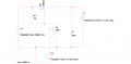
I have gone into LTSpice and tried to simulate a linear regulator that I seen online to help deal with the pulsed output. I will attach a schematic and a waveform capture. The effect of the pulsed output is eliminated and the output voltage is constant. However, voltage across BJT is the output voltage. Does anyone have any other circuit recommendations or improvements to this one.
 

Attachments

MisterBill2

Joined Jan 23, 2018
28,059
You can use a fast opto-isolator to separate the voltages of the power side from the voltages and common reference point of the control circuit. That is done frequently.In addition, you will not have as fast rise times and decy times for the output voltage when you have a capacitor across the load, as shown. The capacitor needs to be on the supply side of the switch.
And the only application that I am aware of for pulsed high voltage like that to a TWT is for radar. And there is a whole world of radar circuit knowledge that I am not familiar with, but it is available to use. You are looking at a realm that I have not studied, only looked at, and that was quite a few years ago.
 
Last edited:

Thread Starter

SiCEngineer

Joined May 22, 2019
444
You can use a fast opto-isolator to separate the voltages of the power side from the voltages and common reference point of the control circuit. That is done frequently.In addition, you will not have as fast rise times and decy times for the output voltage when you have a capacitor across the load, as shown. The capacitor needs to be on the supply side of the switch.
That sounds interesting. If you could spare 5 minutes, could you quickly sketch what the circuit would look like with an opto-isolator? I am quite confused how this would look.

Also, so move the capacitor from where it is now (RHS of the FET and BJT) to the LHS of them? Am I understanding correctly?
 

MisterBill2

Joined Jan 23, 2018
28,059
That sounds interesting. If you could spare 5 minutes, could you quickly sketch what the circuit would look like with an opto-isolator? I am quite confused how this would look.

Also, so move the capacitor from where it is now (RHS of the FET and BJT) to the LHS of them? Am I understanding correctly?
Yes, on moving the capacitor to the left (upstream) side of the switch. As for the circuit with the isolator, I do not have drawing capabilities on this computer, so that part is delayed. But opto-isolator application notes do exist, so check with the manufacturers on their websites.
 

Thread Starter

SiCEngineer

Joined May 22, 2019
444
Yes, on moving the capacitor to the left (upstream) side of the switch. As for the circuit with the isolator, I do not have drawing capabilities on this computer, so that part is delayed. But opto-isolator application notes do exist, so check with the manufacturers on their websites.
Okay, thank you. I have seen opto-isolator circuits in isolated supplies frequently. However I have not ever seen it in this circumstance. There is no rush, I can wait.
 

Thread Starter

SiCEngineer

Joined May 22, 2019
444
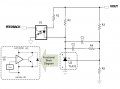
Attached is what I know of a typical opto-coupler, for a flyback circuit for example. However I do not see how I could use this with the linear regulator I showed because the transistor will still need to be connected in parallel across the load (-6kV). Am I not understanding correctly? opto.jpg
 

MisterBill2

Joined Jan 23, 2018
28,059
OK, Now I see the circuit and it looks like the high voltage switching is part of the circuit already, The capacitance to support the delivery of power will need to be where the capacitor to the right of R10 is in the circuit drawing shown.
I wonder just what you are using for a switch in that circuit.
The use of four voltage doublers in series is a bit similar to what I saw published in QST magazine a while back. It makes a lot of sense and really is a good choice for high voltage supply work. So it is a quite good design, although there are several elements that are rather undefined. Or is that where you are in the design process?
And I finally located that article, only to find that the details are referenced elsewhere. But that article is in the January 2017 issue of "QST" magazine.That supply is about 3300 volts at almost an amp, and it uses a 60Khz switching frequency and a small filter capacitor. But the article also has several well described references that may be useful.
 
Top