SUCCESS STORIES: Repair thermoelectric cooler

hoffmma

Joined Oct 21, 2020
1
Hello, I am posting to say thank you for all who contributed to this. I was able to follow the instructions and repair the pcb on our newair wine fridge, same model as what "teamstarlet" posted. I replaced all the caps and transistors as they did. 11 of the originals were bad/had low esr. I used my dvm and also used a mesr-100 for testing on the board but found the little caps difficult to test while in the circuit. I ended up just pulling them all for bench testing which was much easier. I didn't have any burning at the transistors but replaced them anyway since I was at it.

Thanks again.
 

sjervey

Joined Nov 20, 2020
2
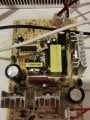
Hello everyone. I have found a NewAir dual level wine cooler. The power boards boards are both labeled MP-012 (very similar to the FX boards mostly discussed here). The bottom board is working OK but the top board had DD1 blown up with a big char mark on the board. After reading all of the posts on this forum I measured all of the parts I could with my DMM and had a laundry list of parts to replace: Input Fuse, T6, T7, DD1, D13, D14, D16, D17, and ALL of the electrolytic caps. After this the board powers up but is not producing the correct DC voltages. I'm getting about 3.2VDC at the TEC leads without connection. If I attach the leads it pretty much goes to zero. The full wave bridge rectifier and voltage double circuit are working as they compare between the working and non-working board. Red LED is on but not as bright as the other board. Not sure where to go from here. Any suggestions?
 

sjervey

Joined Nov 20, 2020
2
Are you maybe missing a solder blob jumper near the big filter electrolytics like I did here?
My board actually required a solder blob between C12- and C15+ (which is C21- and C20+ on the schematic you referenced). The connection from the diodes to the Cap C12+ is in the board layout. Still searching for the problem....
 

Macnc

Joined Apr 20, 2019
11
I have a wine enthusiast 48 bottle dual zone wine cooler. One of the boards no longer has the green or red light coming on. How can I figure out what to replace on the board to get it working again.
 
Hello -

I'm hoping someone who has more intimate knowledge about circuits and particularly the FX-101 board (and its variants FX-101B and FX-102) described here.

I stumbled upon this thread too late and was investigating why my wine cooler (Wine Enthusiast 24-bottle, dual zone) started making chirping sounds the the top section was not cooling.

To quote similar post in this thread:
I have a Wine Enthusiast wine cooler with two FX-101B PCB120606F1 boards, each of which has a two-pin peltier connection. The cooler turns off shortly after starting if the top peltier is connected to the top board, but will work if I leave the top peltier unplugged until after the cooler has started.
I was trying to determine what "component" was failing: TEC, external fan, or circuit board. Since my unit has identical top and bottom units I *stupidly* tried to switch the fan and TEC components from the top board to the bottom. During my "investigations" unplugging and plugging in wires, I suddenly heard a loud "pop" and saw a flash of light. The fuse on the top board (which previously was fine and in-tact) had blown.

I can't recall exactly which wires I had connected to which board at this point, but needless to say with a fuse blown I figured nothing was going to work until I repaired that.

I ordered a few matching fuses (250 V, 2.5 A) and soldered a replacement in. I attached all the top board's wires: power, fan 1, fan 2, TEC, and control unit. As soon as I plugged the unit in, another pop and flash. Top board fuse blown...again. Back to the soldering iron and with another new fuse in, this time I plugged in all the wires but the top TEC and fan. As soon as I powered on the unit, another pop and flash. I have two more replacement fuses but at this point, I'm trying to understand what would cause the fuse to blow immediately after supplying power. Should I not connect any of the external components and power up the board?

So for those who are more savvy with electronics and circuits, I'm generally trying to understand why a fuse would blow immediately. I know the purpose of a fuse is to blow if the current pulled over it exceeds its design to prevent damage to other parts of the board/circuit. But does this mean some other resistor, transistor, capacitor, etc. after the fuse is faulty/damaged such that it's causing way more amps to be pulled across the fuse then expected?

In hindsight, I probably could've replaced the C8 capacitors like many folks have suggested...and it would've been fine but I messed around with it to the point where now the fuse is blowing instantly with power and I'm not sure i have the desire to replace every single transistor, resistor, and cap on the board at this point.

Could I use a digital multi-meter to help find the culprit component or issue? Anyone have ideas/suggestions?
 

kcvogels

Joined Dec 22, 2020
2
probably 1 or 2 diodes from the input bridge are broken,replace all 4 (1n4007) but you have to measure the two transistors in the main part of the circuit ,if 1 or two are broken,also check base resistor 2 ohm and diode in base circuit. I replaced transistor and resistor and it worked,but you could hear not good,then it appeared that the base diode was interrupted.
 
probably 1 or 2 diodes from the input bridge are broken,replace all 4 (1n4007) but you have to measure the two transistors in the main part of the circuit ,if 1 or two are broken,also check base resistor 2 ohm and diode in base circuit. I replaced transistor and resistor and it worked,but you could hear not good,then it appeared that the base diode was interrupted.
Hmm. So you replaced the input bridge diodes and the resisters in main and base?
 

topwing

Joined Dec 17, 2020
1
Hi all,

Just wanted to say thanks for this thread. I read through every post to try to learn how to fix a HomeImage wine fridge my friend gave me. The top fan was not working, and the two boards inside were labeled PCB130312K8. They're a bit different than others I've seen in this thread, but pretty close.

After reading all the info here, I decided to order two full sets of new capacitors, totaling about $25 on DigiKey. I was planning on spending a long afternoon replacing them all, but I wanted to start simple. Based on the comments, I decided to replace only the C8 capacitor and test it out before doing the rest. Sure enough, the fridge works perfectly after replacing C8.

P15141-ND

Thanks again to everyone who contributed here.
 

AB2021

Joined Jan 2, 2021
1
The sensors seem to be working, but not my chiller is cooling to to the low 40s. Clearly something has changed - Ive made it too efficient!. It seems my replacement caps have upset the balance but I dont see how to re-balance the circuit at this point. Any suggestions appreciated.
Mine runs after a cap change but its over cooling now - just wont stop. Does anyone have any ideas - its not turning off when it reaches the set temp.
I successfully repair my Haier 8 bottle wine cellar with cap replacing but get a similar problem like StanAccy.
StanAccy, did you solve it?
 

eredi93

Joined Sep 16, 2020
1
One more success story!

My in laws had a wine fridge which was not cooling in the basement for almost 10 years, I decided to try to fix it and after some time trying to reverse engineer the board I came across this amazing thread.
I changed the caps and fuse and now is working perfectly!

Thanks everyone for sharing the diagrams and your stories! I don't think i would have been able to fix it without your help ‍♂
 
So i stopped by my parents place today and their Wine Enthusiast dual-zone refrigerator crapped out So after a bit of trouble shooting, here is what i found.

- Plugged in, the lower FX-101 shows a red light and fan spinning, the top PCB shows no light and no fan, front screen is not working.
- Disconnecting the TEC from the upper board, plugging in makes both FX-101's power up with red and green illuminated + front display works.
- TEC tested to be functional using bench power supply. opposing sides got hot and cold @ 6v and 2.6a. I then upped the voltage to 10.5v and slowly increased the current and at 10.5v it was drawing 4.4a. My limited experience with TEC coolers says this is not abnormal and that they're serious power hogs.

- I have yet to check the output voltage of the upper FX-101 but i'm guessing the board is not able to supply enough power to both the TEC and the front display. Bad caps?

*begins reading thread*

edit/
I just now realized i've been a member of this forum since 2013 yet this was my first post.
 
So i just hooked everything back up EXCEPT for the TEC and like before, everything powered up, green lights on both FX-101's and the front panel lit up. I checked the voltage on the upper board that i suspect has bad caps and the output voltage is 10.5v.

The moment i connected the TEC, the voltage drops to 1.1v and the whole thing craps out.

Am i still correct in thinking its the capacitors? they're cheap so ill just order the whole lot of them. All capacitors replaced for $6 plus shipping which was another $6. I had to go with 250v on the two 120uf caps since none were in stock of the normal ratings. If anyone is wondering, i bought the stuff from arrow.com
 
Well i decided to desolder C8 and C10 and check them out and C10 tested just fine. C8 on the other hand was WAY below spec, down in the nano-farad range. So on a whim i looked over a broken PC power supply i used to use for testing and powering the pumps on and off when refilling the custom loop in my PC (spilled some coolant and POOF) and on the PCB was a 50v 47uf (C8 is 25v 47uf) capacitor, so i soldered it in and the fridge fired right up perfectly.
I guess ill just hang onto the capacitors that i ordered and if the fridge craps out again, ill replace the whole lot of them.

Thanks again for the wealth of information on fixing these things. I probably would have just bought a new power board had i not found this thread since there was nothing visibly wrong with the PCB and while i have no problem physically doing repairs, i'm greatly limited due to being self taught
 

Thread Starter

wayneh

Joined Sep 9, 2010
18,181
Well i decided to desolder C8 and C10 and check them out and C10 tested just fine. C8 on the other hand was WAY below spec, down in the nano-farad range.
Glad to hear you got it going!

You're "lucky" that it had failed so badly. They usually fail first on ESR, which most meters don't measure. They can look fine on capacitance but completely fail due to ESR. Your replacement may not last long if it isn't rated for the duty it is now in. But you'll be ready.
 

Steveorama

Joined Feb 9, 2021
14
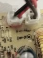
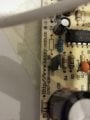
Can someone please help. I've got a broken Kemin fridge that has this board (or similar). It looks like it's had a short and blown two resistors where the dc power comes in. One is labelled da1. I can't see the label on the other.
Does anyone know what I should replace them with please?
Thanks in advance.
 

Attachments

Steveorama

Joined Feb 9, 2021
14
Can someone please help. I've got a broken Kemin fridge that has this board (or similar). It looks like it's had a short and blown two resistors where the dc power comes in. One is labelled da1. I can't see the label on the other.
Does anyone know what I should replace them with please?
Thanks in advance.
Sorry, I meant 2 diodes!
 
Thread starter Similar threads Forum Replies Date
SgtWookie Off-Topic 4
Top