SUCCESS STORIES: Repair thermoelectric cooler

JoeJester

Joined Apr 26, 2005
4,390
This thread alone has converted me to a believer in the “replace the caps” approach to PCB repair.
I found using an ESR checker to be indispensable when checking the electrolytics. Now in a personal system, if someone wanted to wholesale replace capacitors, I have no objections as it is their money. Customers on the other hand, might object if you didn't test them.
 

MrAl

Joined Jun 17, 2014
13,859
This thread alone has converted me to a believer in the “replace the caps” approach to PCB repair.
Hi,

That's how i fixed several of my products in the past, although i did test the caps too after removing them and found many to have very very high ESR and very very low capacitance. The ESR was typically 10 times higher and the capacitance 10 times lower, which in a power supply circuit is not acceptable for correct operation.
I found the most likely caps to fail are the ones used in the power supply that have to handle significant current such as in the filter circuits.

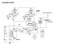
These cooler circuits i think can be broken down in to three main sections:
1. The power supply.
2. The control circuit.
3. The thermoelectric cooler module.

Since the power supply has to handle currents of maybe 6 amps or more, that's the most likely to fail first.

The thermoelectric cooler module is easy to test. Just apply current of maybe 1 to 3 amps and make sure one side gets cold and the other side gets hot. This test should only be performed for maybe 1 minute or less with no heatsinks, or longer if the heat sinks are still installed.

The controller circuit will be harder to figure out because there are many variations.

To totally rebuild something like this would be quite easy. The hardest part would be building a power supply that can handle the full current. The controller part is literally cake with modern IC chips like the LM339.
To fill in for the power supply, an interesting alternative is to purchase a high current "wall wart" like the kind that have a line cord (they dont plug into the wall like an ordinary wall wart but have a long cord that plugs in). Tehse are available at many different voltages and currents, even 12v at 6 amps for example. To get to the right voltage if you have a higher voltage wall wart, you can use a buck circuit which isnt hard to build these days either, but if you get the right voltage you wont even need that.
So let's say you use a wall wart of the right voltage and high enough current. All you need then is a thermistor or two and a simple control circuit that can be made with an LM339 and a power transistor and maybe an intermediate power driver transistor. If the thermo cooler device still works, you've got all you need to completely rebuild this thing and the nice thing is, now it is very easy to repair because you know where all the parts came from and you can simply buy them again if you really need them.
This would of course even work for a built from scratch unit although you do need decent heat sinks.
The circuit is so simple anyone could build one, and if need be, rebuild it after a failure.
I would bet that there are multiple LM339 or similar based temperature controller circuits on the web. A window comparator would be the basic idea.
 

hueypic

Joined Sep 12, 2017
10
Were they really in series, electrically?
No, no.... Sorry, I misspoke. They were of course in parallel. Verified with a continuity tester between the two positive and two negative spots on the PCB.
Since I am trying to remember things from high school physics some 37 years ago, I had to rely on google and a picture, but at least I had a slight recall that mathematics was almost opposite to that of resistors.
 

NoSale

Joined Oct 28, 2017
2
I have been following this thread and have referenced in in the past. My Frigidaire wine cooler started chirping about a year ago. I discovered that if I disconnected one of the plugs on the circuit board, the chirping stopped and the fan kicked on. I found that then re inserting the plug, the cooler functioned properly with no chirping. In essence, I suspect I just reset something.

However, that only lasted about a year. The chirping is back and I can't get the reset procedure to work again.

In this thread there were other solutions, but I don't have the circuit know how or soldering skills to go through the steps documented here that were successful. It seems some have indicated the FX-101 board is no longer available and replaced by a FX-102 board. However, I found the FX-101 board is available from a US distributor:

https://haier.encompass.com/item/8452582/Haier/RF-5210-110/P.c.b._-_Power

I ordered this today and hope it will resolve my issue. If not, I'll find another thermoelectric cooler. But at least I can make another stab at fixing by buying the pcb........
 

Thread Starter

wayneh

Joined Sep 9, 2010
18,181
I have been following this thread and have referenced in in the past. My Frigidaire wine cooler started chirping about a year ago. I discovered that if I disconnected one of the plugs on the circuit board, the chirping stopped and the fan kicked on. I found that then re inserting the plug, the cooler functioned properly with no chirping. In essence, I suspect I just reset something.

However, that only lasted about a year. The chirping is back and I can't get the reset procedure to work again.

In this thread there were other solutions, but I don't have the circuit know how or soldering skills to go through the steps documented here that were successful. It seems some have indicated the FX-101 board is no longer available and replaced by a FX-102 board. However, I found the FX-101 board is available from a US distributor:

https://haier.encompass.com/item/8452582/Haier/RF-5210-110/P.c.b._-_Power

I ordered this today and hope it will resolve my issue. If not, I'll find another thermoelectric cooler. But at least I can make another stab at fixing by buying the pcb........
Let us know how it goes. This should be a viable option for anyone not interested in replacing caps and other parts.
 

hueypic

Joined Sep 12, 2017
10
I have used Encompass before and found them to be pretty good at finding very obscure parts. Very fast shipping, if I recall correctly.
 

MrAl

Joined Jun 17, 2014
13,859
Hi,

I am hearing about these failures more and more these days. I am wondering if it is getting close to the time to design a low cost control circuit that can replace any of the control circuits for these things and would be easy to troubleshoot and fix. The nice thing about designing a circuit and building it is that we know what all the parts do and we know how to get the replacement parts, and with a little thought we can use parts that will always be available.
I have a cooler too but it's just the thermo device and the two heat sinks and two fans. Tested it but did not use it for anything yet. I can see how simple these things are though. When you want cooling, you just turn the dang thing on as well as the fans. To make it respond to temperature, just use a thermistor and a LM339 and a decent pass transistor. The only thing left then is the power supply which can be a heavy duty 12v wall wart.
 

N11778

Joined Dec 4, 2015
176
Try posting a photo.
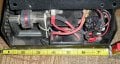
I put it back together. No markings on the 1" square 2" long rectangle Black plastic box.
2 larger red wires and two black ones coming out.
The two red ones are the high voltage. Some kind of Multiplier like used in the old tv sets.
 

Thread Starter

wayneh

Joined Sep 9, 2010
18,181
I put it back together. No markings on the 1" square 2" long rectangle Black plastic box.
2 larger red wires and two black ones coming out.
The two red ones are the high voltage. Some kind of Multiplier like used in the old tv sets.
Maybe a coil? My barbecue grill igniter has a 'black box' in it that sounds a lot like what you've described. It resembles the copper coil you can see here:
 

NoSale

Joined Oct 28, 2017
2
I have been following this thread and have referenced in in the past. My Frigidaire wine cooler started chirping about a year ago. I discovered that if I disconnected one of the plugs on the circuit board, the chirping stopped and the fan kicked on. I found that then re inserting the plug, the cooler functioned properly with no chirping. In essence, I suspect I just reset something.

However, that only lasted about a year. The chirping is back and I can't get the reset procedure to work again.

In this thread there were other solutions, but I don't have the circuit know how or soldering skills to go through the steps documented here that were successful. It seems some have indicated the FX-101 board is no longer available and replaced by a FX-102 board. However, I found the FX-101 board is available from a US distributor:

https://haier.encompass.com/item/8452582/Haier/RF-5210-110/P.c.b._-_Power

I ordered this today and hope it will resolve my issue. If not, I'll find another thermoelectric cooler. But at least I can make another stab at fixing by buying the pcb........
Just to update my own post.

As hueypic indicated, fast ship from Encompass. It arrived within a few days (ordered Sunday night, arrived Thursday via FedEx) and was exactly the same as the board that was failing. Board replacement took 5 minutes (screws to mount and just connect in a few board plugs). Plugged in and all was working. Project done.

Replacing the board may not have been the most economical (total cost was about $31) or rewarding/challenging, but it was cost effective and easy. Plus for my limited skills, it was still fun.

Now, I might take that old board and figure out where the failure was, or take a soldering iron to it to disassemble :)..........
 

K6216

Joined Jul 23, 2017
21
Since I scored another cooler in a dumpster recently, and it used an FX-101 supply, I thought I'd list the values of all of the capacitors and their ESR. I will try to attach a pdf of the xlsx file. Note the column with * flagging the real bad caps. I suspect that C8 & C10 are what keep this supply from working. Also the main input caps are likely ok and expensive to replace >$2 ea. Also note the measured capacitance for each cap. All but C10 are in reasonable range of the label value. That is why you must use an ESR meter to evaluate eCaps. I'll replace all the caps and report the result. Waiting for cap delivery.
 

Attachments

K6216

Joined Jul 23, 2017
21
Check the ESR of some of the new caps when you can. I think you'll find lower values than the "good" levels in your list. Just a hunch.
I would agree. The numbers I posted are from the web and likely represent worst case. My point was that if measured ESR is lower than the noted, the Cap is ok. (All else being equal). Visual inspection is important too.
 

K6216

Joined Jul 23, 2017
21
I put it back together. No markings on the 1" square 2" long rectangle Black plastic box.
2 larger red wires and two black ones coming out.
The two red ones are the high voltage. Some kind of Multiplier like used in the old tv sets.
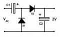
It's very likely a diode/capacitor voltage multiplier. Likely a diode/cap ladder multiplier, stack-able for higher voltage.
 

Attachments

Thread starter Similar threads Forum Replies Date
SgtWookie Off-Topic 4
Top