Substitutes for Components I cannot find/buy in My Place

OBW0549

Joined Mar 2, 2015
3,565
This is something from the site written by the author: "The signal coming from the guitar, however, is very low in amplitude and oscillates around 0 V, meaning it contains some negative voltages that the Arduino cannot read.". The input signal is coming from an electric guitar and I don't know if the signal coming from the guitar is considered as extremely low.
Your second trace, of the guitar signal without the amplifier, shows a signal of approximately 50-70 mV peak value; I wouldn't consider that "extremely" low, so I think you can dispose of your concerns about op amp noise; the MCP6002 should work quite well.

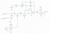
Sir, I've already tested the amplifier circuit on Simulink and it wont send any signal to the arduino. Whenever I strum a string, there are no changes in amplitudes, just a straight line. I've run a simulator and here is the image. It's on a 5s period.
I'm baffled by that result; the amplifier circuit, just as you've shown it, should work and should give you a gain adjustable from about 1.2 to 22. I can't see anything wrong with the amplifier design. Perhaps someone else could comment.

I've tested the guitar without the amplifier circuit on simulink and as you can see, whenever I strum a string, there's changes in amplitude.
I find it odd that the waveform only goes positive relative to ground; I would expect it to go both negative and positive, and I can't understand why it doesn't.

I'm not familiar with Simulink, so I can't suggest might be wrong with your simulation. I assume something isn't right, since the results you are getting don't seem to make sense.
 

Thread Starter

Alyssa 1

Joined Feb 13, 2019
18
Your second trace, of the guitar signal without the amplifier, shows a signal of approximately 50-70 mV peak value; I wouldn't consider that "extremely" low, so I think you can dispose of your concerns about op amp noise; the MCP6002 should work quite well.
Okay sir. Thank you for letting me know.

I'm baffled by that result; the amplifier circuit, just as you've shown it, should work and should give you a gain adjustable from about 1.2 to 22. I can't see anything wrong with the amplifier design. Perhaps someone else could comment.
It's already 11pm on my place sir, I'll go to an electronics technician first thing tomorrow because there might be complications on the pcb that I've made. He might be able to solve my problem. I'm not really good in electronics sir and I only know about the basics so I'm trying real hard to learn from crash courses on the internet and from these forums. Thank you so much for helping me.
 

Thread Starter

Alyssa 1

Joined Feb 13, 2019
18
I find it odd that the waveform only goes positive relative to ground; I would expect it to go both negative and positive, and I can't understand why it doesn't.
It's a simulation of the signal on Simulink sir coming from the Arduino board and the author said on his site that the negative voltages cannot be read on the arduino board, the arduino board can only read between 0v to 3.3v. That's explains why there's no negative signals relative to the ground shown on the simulation. That's why an amplifier circuit is needed to amplify the signal coming from the guitar.
 

Ylli

Joined Nov 13, 2015
1,092
Simulink is a simulator. How are you looking at the output of a guitar on a simulator? What exactly is that second picture (of the guitar output) looking at?
 

ian field

Joined Oct 27, 2012
6,536
Two 4.7 uF caps. These are standard values and you should be able to find them. The values are not critical, and anything near 4.7 uF or more would be OK. I'm sure two 2.2 uF in parallel would be close enough.
Common general purpose capacitors have pretty loose tolerances anyway - I've seen (-)50%/(+)100% on some aluminium electrolytics. The "odd" values for the higher series range will have closer tolerances though.
 

ian field

Joined Oct 27, 2012
6,536
680p will most likely be fine instead of the 620p. I'd use a 15 nF to replace the 13.6 nF listed. These subs will have a very small effect on the frequency response of the circuit, but i don't think frequency response is a critical parameter here.

[and I'd suggest a 1N4148 for the output diode. If you have already ordered the 1N400x, that's OK too, but will likely have higher leakage than the 1N4148]
620pF is a standard part in the higher precision series - 13.8pF is a custom value. Have a little think about why they bothered going to all that trouble...……………..
 

Thread Starter

Alyssa 1

Joined Feb 13, 2019
18
I can't see anything wrong with the amplifier design. Perhaps someone else could comment.
Hi sir, sorry for my very late reply. There's nothing wrong with the amplifier and I have discovered that pin_A0 was shorted to the pcb's ground that's why the simulation always shows a straight line and shows little changes when I tap on the pcb's copper clad. The amplifier works now sir. Thank you so much for your big help and to everyone who have helped me, thank you very much.
short.png
 
Top