Facebook
 Google
 GitHub
 Linkedin
Hey All,
I am new to electronics repair. Before spending a couple of grand to replace a thermostat with a malfunctioning screen, I am attempting a repair suggested on the following forum:
https://www.ifixit.com/Guide/Lennox+iComfort+10F81+Thermostat+Blank+Screen+Fix/156024
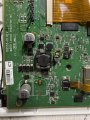
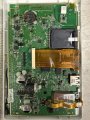
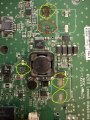
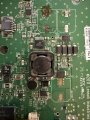
Unfortunately, when removing the capacitors, I stripped most of the contact pads. I’ve attached a few images of the board and the damage I’ve caused.
I am able to remove the pads from the old capacitors, but how do I attach them back to the board (get them to stick)?
Also, aside from the pad slot I circled in red, it’s not clear to me what wires the other pad slots are connecting to.
If anybody has any advice or recommendations for what to try next, I’d appreciate it!
I am new to electronics repair. Before spending a couple of grand to replace a thermostat with a malfunctioning screen, I am attempting a repair suggested on the following forum:
https://www.ifixit.com/Guide/Lennox+iComfort+10F81+Thermostat+Blank+Screen+Fix/156024
Unfortunately, when removing the capacitors, I stripped most of the contact pads. I’ve attached a few images of the board and the damage I’ve caused.
I am able to remove the pads from the old capacitors, but how do I attach them back to the board (get them to stick)?
Also, aside from the pad slot I circled in red, it’s not clear to me what wires the other pad slots are connecting to.
If anybody has any advice or recommendations for what to try next, I’d appreciate it!
Attachments
-
 2.1 MB Views: 15
 -
 1.2 MB Views: 15
 -
 1.5 MB Views: 14