Stray AC voltage on transformer?

Thread Starter

kennybobby

Joined Mar 22, 2019
75
Where and how is this stray voltage created? Is there a simple solution to squash it? It is causing the LEDs to illuminate faintly even with the main switch S1 OFF.

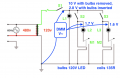
Here is a diagram of the situation. 2 legs of the 3-phase mains runs to the primary of a stepdown trnsformer; the 120vac secondary has one side tied to chassis that is tied to Prot. Earth Ground back at the 3-phase mains box.

The 120 V LEDs used in the bulb sockets don't measure any voltage drop, but will very faintly illuminate with a DMM diode check. With the bulbs out i read about 10vac as shown from the downstream side of S1 to GND. With bulbs in it drops as shown.

i've read about capacitive coupling, but don't understand where it occurs or how to eliminate it. i need some clues to this mystery.
 

Attachments

MrChips

Joined Oct 2, 2009
30,720
If this is a real setup here are my observations.

1) You need to install a fuse followed by an ON/OFF switch where AC power comes in, not after the transformer.

2) Even as it is, there should be no measurable voltage on the bulb side of the circuit if S1 is truly open. If there is then something is amiss that you cannot see.
 

Papabravo

Joined Feb 24, 2006
21,159
It is possible that those readings are an illusion. When a DMM is measuring an AC input there is no indication about the frequency content of what is being measured. If what is being measured is at the power line frequency you would have reason for concern. All that wire is just a big fat antenna. If you are still concerned you need to take some readings with an oscilloscope or a spectrum analyzer.
 

nsaspook

Joined Aug 27, 2009
13,086
As was said in post #2. Switch off the power at the primary side if the low energy electric field (causing stray voltage potentials across high impedance components) from always on secondary wiring is a problem.
 

michael8

Joined Jan 11, 2015
410
Those readings may not be an illusion (but confusing). Your diagram
may be incomplete, missing some "components" you don't usually think of
as components.

I have a room with a ceiling lamp holding a LED light. The 120VAC/60Hz
power feed goes to the light fixture and two wires run across the ceiling
and down by the door to the light switch.

The resulting circuit with the switch off is that the LED is in series
with the capacitance between the wires to the (off) switch. Even though
the total wire run from the lamp to the switch is only about 11 feet
there is enough current flow for the LED to be visible when the room is
dark and the eyes are dark adapted.
 

Thread Starter

kennybobby

Joined Mar 22, 2019
75
This is a real circuit; it is in the control cabinet of a portable leveling actuator used with an overhead crane. It is seldom used 1 week a year, but the techs pointed out to me that the lights were always faintly lit, even when in E-Stop (S1 Off). That's when i was called in to investigate.

i did notify the designer that there was no fuse to the primary and suggested that be added. Due to the infrequent usage, he may have decided that the disconnect box for the 3-phase mains could function as the ON/OFF switch for the system.

The switches drive the coils in 4-pole contactors (M1..) that supply 3-phase to the motor control section, the fourth contact is shown for the LED indicator for that switch.
 

Thread Starter

kennybobby

Joined Mar 22, 2019
75
The L1 is brighter than all the rest, but all the LED bulbs are faintly illuminated when OFF, and definitely noticeable at night or in a dark room.

So even though one side of the secondary is grounded, there are stray voltages due to capacitive coupling into the various wires by the electric field of the high side of the secondary to ground?
 

nsaspook

Joined Aug 27, 2009
13,086
The L1 is brighter than all the rest, but all the LED bulbs are faintly illuminated when OFF, and definitely noticeable at night or in a dark room.

So even though one side of the secondary is grounded, there are stray voltages due to capacitive coupling into the various wires by the electric field of the high side of the secondary to ground?
A LED is a current (light EM created from small charge movements) device so the intuitive way to see how the AC circuit is causing the dim LED lighting is with a current source. Because at X location from the electric field, the electric field (with a voltage potential up to 120 VAC) can provide X amount of current from that point to a ground reference as a current source feed (maybe tens of uA) for the LED at the forward voltage needed.
 

Thread Starter

kennybobby

Joined Mar 22, 2019
75
Thank you all for the helpful replies, i needed to get an intuitive feeling for how this can happen, and learned something i probably should have known.

The LED bulbs only have 120V written on the miniature bayonet base. They don't seem to have any polarity and come ON with the DMM diode function check from both directions.

The current source concept was a great help for understanding this; i was looking for something to provide or induce a current path, and by the wiring diagram none should exist. Yet i saw it happen.

i checked and rang out each wire to verify the circuit diagram, and was beginning to think i missed something, but it is almost too simple for such a blunder on this.

Next week i'll put a scope on it to see what frequency is there, and run a test with a suitable resistor across a lamp terminal to provide a leakage path to bleed off any charge build up.
 

Thread Starter

kennybobby

Joined Mar 22, 2019
75
i scanned inside the cabinet with a Magnetic Field probe (small 1” diameter antenna loop) while S1 was open and i could see no signal on the o’scope. This makes sense since there is no current flowing when the circuit is OFF.

Then i used an Electric Field probe (short monopole antenna) and was picking up stray 60 Hz AC in the vicinity of all the wiring going to the switches and lights. It was the strongest when near the Primary wires running to the transformer, which makes sense since that has the highest voltage swing of 480 vac between each other and about 240 vac each to earth ground chassis even with S1 OFF.

i put a 100k resistor across the light terminals on L1 and the DMM voltage measurement dropped to about 0.121 vac and the LED no longer was lit. This would solve the dimly lit when OFF issue, but there should also be an ON/OFF disconnect for the 3-phase mains to cut off power to the primary and a fuse in the wires to the primary.
 
Top