Facebook
 Google
 GitHub
 Linkedin
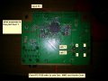
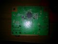
I got a strange problem with this PCB but i will mention it later. Before i ask some advanced users for help i want to try it by mine self.
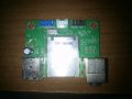
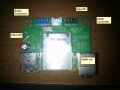
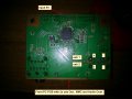
Question for now is how to found diagram for this PCB ? I try couple of names but seem to have no results
Thank you guys in advance
Question for now is how to found diagram for this PCB ? I try couple of names but seem to have no results
Thank you guys in advance
Attachments
-
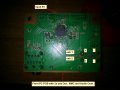
 761.6 KB Views: 71
 -
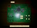
 653 KB Views: 75
 .
.