 Facebook
 Google
 GitHub
 Linkedin
Hi!
Hopefully someone can help me figure out what is going on with my full bridge.
I am using a h-bridge, A4953ELJTR-T (datasheet attached) to control a solenoid. When I activate the the solenoid I use 24 v, but to hold it about 5 v should be enough. But this driver are causing problems.
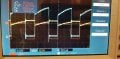
When I connect a resistive load to the h-bridge, run a pwm signal and put the probes across the resistor I get some strange curves.
Blue and yellow is the voltage across the resistor (200 ohm). Subtracting on from the other gives the red curve, the nice pwm signal.

So it seems the H-bridge increase the voltage on both terminals to reduce the potential across the load instead of have more "off time". Maybe this is a common method? Does anyone know what its called? It likes to do this at lower duty ratio and it makes sense.
Now the problem I was having was the solenoid would drop out at around 50% (12v) duty cycle if running with this h-bridge, 15% (3.6v) if running from a lab psu. This is regardless of the frequency. Same results with 30 khz and 3 khz.
I tested with a "normal" half bridge and the results were similar to that of the lab PSU (dropped out around 20%).
If I slowly decrease the duty cycle i notice something like a really quick (<1s) "phase shift" around 50% duty cycle, the oscilloscope trigger is unable to center the signals for a brief time. My guess is that the driver is perhaps modifying its behavior and this interruption is causing the solenoid to drop out so early.
Perhaps I have misunderstood the whole situation, not sure. But if anyone could shine some light on this I would very much appreciate it!
Hopefully someone can help me figure out what is going on with my full bridge.
I am using a h-bridge, A4953ELJTR-T (datasheet attached) to control a solenoid. When I activate the the solenoid I use 24 v, but to hold it about 5 v should be enough. But this driver are causing problems.
When I connect a resistive load to the h-bridge, run a pwm signal and put the probes across the resistor I get some strange curves.
Blue and yellow is the voltage across the resistor (200 ohm). Subtracting on from the other gives the red curve, the nice pwm signal.
So it seems the H-bridge increase the voltage on both terminals to reduce the potential across the load instead of have more "off time". Maybe this is a common method? Does anyone know what its called? It likes to do this at lower duty ratio and it makes sense.
Now the problem I was having was the solenoid would drop out at around 50% (12v) duty cycle if running with this h-bridge, 15% (3.6v) if running from a lab psu. This is regardless of the frequency. Same results with 30 khz and 3 khz.
I tested with a "normal" half bridge and the results were similar to that of the lab PSU (dropped out around 20%).
If I slowly decrease the duty cycle i notice something like a really quick (<1s) "phase shift" around 50% duty cycle, the oscilloscope trigger is unable to center the signals for a brief time. My guess is that the driver is perhaps modifying its behavior and this interruption is causing the solenoid to drop out so early.
Perhaps I have misunderstood the whole situation, not sure. But if anyone could shine some light on this I would very much appreciate it!
Attachments
-
 151.3 KB Views: 4
 -
 153.4 KB Views: 4
 -
 155.1 KB Views: 4
 -
1,003.4 KB Views: 4
-
 152.2 KB Views: 5


