strange buzz problem with input stage of home-made chip amp.

Thread Starter

Aivaras Andrijauskas

Joined Aug 26, 2019
41
No buzz is present, when connection on input stage is unconnected
amp1.jpg
no buzz i present when wire connected to input stage, leads connected together- picture 2
amp2.jpg
however, plugging in the wire, with + and - leads open, produces buzz when amp turned on. buzz intensifies, when i touch/squeeze the insulated parts of the lead wires (how? they're insulated). connecting the leads to mono jack for guitar, leaves identical noise. (connecting guitar to this setup, produces sound, but with a weird, lazer/star wars sounding overtone/echoe of each note, which plays half a second after each note is played)

if the open leads are the problem, why no noise in picture 1? isn't the wire just extending the leads? so why the noise, when unconnected wire plugged in?
and how do i eliminate the noise?
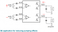
How do i create an input stage, that doesn't buzz when open?
 

AlbertHall

Joined Jun 4, 2014
12,346
Your body picks mains noise and RF signals. When you hold the wires, the capacitance between the wires and your fingers passes this noise on to the wires.

Maybe use screened cable for the input. Even twisted pair cable might be better.
 

Thread Starter

Aivaras Andrijauskas

Joined Aug 26, 2019
41
i have shielded wire.
but how do i ground the shield?
i have a gnd connection on my power source, but it's literally just the gnd connection from the power socket (eu style).

so I wire one end of the shield to the ground connection on my power supply, and leave the other end unconnected? do i connect both ends to the ground? won't that create a ground loop?
 

Audioguru

Joined Dec 20, 2007
11,248
The TDA8932 IC does not have a + input and a - input. Instead it has a + input and the - input should be connected to the circuit's ground.
The signal source should have its 'live" output connected to the internal wire of a shielded audio cable and the other wire of the source connects to the shield wire that connects to the input - ground terminal of the amplifier.
 

Thread Starter

Aivaras Andrijauskas

Joined Aug 26, 2019
41
So here's what i should do, if I understand correctly:

1. connect the + terminal of the 3.5mm mono jack socket to the + input terminal on the chip with a shielded wire.
2. connect the second connection of the mono jack socket to the shielding of the wire.
3. connect the shielding to the - input terminal on the chip.
4. run an additional wire from the - input terminal, to the ground of my circuit.

and the ground, is the ground of my power source (middle connection).
power.jpg

everything correct?
 

Thread Starter

Aivaras Andrijauskas

Joined Aug 26, 2019
41
Should i proceede with the above listed steps?

Basically all i need to do, is:
1. connect the negative input terminal of the chip to ground.

2. connect the + of the mono jack socket with the + input terminal on the chip, with a shielded wire.
3. connect ground of the mono jack socket, with ground, vie the grounded negative input terminal on the chip?

or connect ground of mono jack socket directly to ground, not through - input terminal?
so that the negative input terminal is only connected to ground, no wires going to it?
that's the part i don't get
 

Thread Starter

Aivaras Andrijauskas

Joined Aug 26, 2019
41
So do i need to connect my negative input terminal, to the ground on my power source?

the schematic illustrates multiple connections going to ground, but my amplifier board is not connected to ground.
i haven't seen anyone else do this when using this chip, they just connect two input wires from the source, with nothing anywhere connecting to ground.

I apologize if i'm annoying, i'm just confused on what to do.
 

Audioguru

Joined Dec 20, 2007
11,248
The amplifier is designed for differential inputs. But your signal source is probably not differential. Instead it probably has one signal wire and a ground wire that connects to the cable shield.
The amplifier inputs are already DC biased so they need a coupling capacitors as shown on the datasheet.
You can try grounding your - signal source wire to the amplifier ground or try not connecting it to the amplifier ground.

The BTL inputs and output connections produce much more output power than Single Ended inputs and outputs
What is your speaker impedance and supply voltage?
 

Thread Starter

Aivaras Andrijauskas

Joined Aug 26, 2019
41
Two 4ohm in series, most sources claim 18w per speaker. so ~8ohm, ~36W when i series.
Power supply is DC 24V 2.2A. (24V 2A claimed to be best for this chip)

It was explained to me elsewhere, that the + input terminal connects to the + signal wire, and the - input terminal is the signal ground (it's somehow grounded through the - terminal DC input terminal, if i understood correctly).
I connected the mono jack, with a shielded cable, (+ to +, gnd to -), and it works. not very loud. building a pre-amp circuit right now to improve that.
 
Top