Still stuck on schematics

Thread Starter

Kid347

Joined Aug 14, 2015
70
C4 connects between the +V supply and ground. Those lines represent a wire ... and the dots represent a connection.

If you changed any connections, remeasure the transistor connections to ground.

I don't like the fact that the Q1 base is too low, it should be closer to 0.5 to 0.7 volts. I don't like the fact that Q1 collector is zero. It should be higher, possible about half the supply voltage or more depending on how your DMM samples the signal.
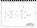
I replaced Q1 I now have .232mv on the collector, but still no sound, are you saying that C4 connects from ground to +5v and nothing else? I don't know what the purpose of the capacitor would be if it does not connect to anything.
 

Thread Starter

Kid347

Joined Aug 14, 2015
70
C4 connects between the +V supply and ground. Those lines represent a wire ... and the dots represent a connection.

If you changed any connections, remeasure the transistor connections to ground.

I don't like the fact that the Q1 base is too low, it should be closer to 0.5 to 0.7 volts. I don't like the fact that Q1 collector is zero. It should be higher, possible about half the supply voltage or more depending on how your DMM samples the signal.
Also does C2 not connect to anything other then +5v and ground? because I have it going from ground to the resistor R1 and to Pin 8. I told you I was lost. but if you look at the attachment of the LM555 Hee Haw Siren I built that circuit with no problem and it works. It just doesn't have all the confusing connections. Any idea why I can follow that schematic and get totally lost in the British Siren?
 

Attachments

JoeJester

Joined Apr 26, 2005
4,390
In the last set of photos you have the 47k potentiometer wired incorrectly.

The wiper (center) is connected to the same point as the capacitor, the other pin of the potentiometer AND that is connected to pins 6 and 2.

Have you read the 555 datasheet? Which 555 do you have? LM, NE, TLC, etc? Ensure you have the datasheet for that chip.

The photos should be taken overhead or at a 45 degree angle, from both sides to see where all the wires are connected.

The hee haw siren used the old method of showing a non connection (jumping over the wire) and it shows the "dot" indicating a connection.
 
Last edited:

Thread Starter

Kid347

Joined Aug 14, 2015
70
In the last set of photos you have the 47k potentiometer wired incorrectly.

The wiper (center) is connected to the same point as the capacitor AND that is connected to pins 6 and 2.

Have you read the 555 datasheet? Which 555 do you have? LM, NE, TLC, etc? Ensure you have the datasheet for that chip.

The photos should be taken overhead or at a 45 degree angle, from both sides to see where all the wires are connected.
Joe I will make the changes and see what happens. Can you tell me how can I go about learning electronics, an online class would be great. I did not see anything in our area for night classes. I would really like to learn it, but I am having a tough time doing it on my own.
 

Thread Starter

Kid347

Joined Aug 14, 2015
70
In the last set of photos you have the 47k potentiometer wired incorrectly.

The wiper (center) is connected to the same point as the capacitor, the other pin of the potentiometer AND that is connected to pins 6 and 2.

Have you read the 555 datasheet? Which 555 do you have? LM, NE, TLC, etc? Ensure you have the datasheet for that chip.

The photos should be taken overhead or at a 45 degree angle, from both sides to see where all the wires are connected.

The hee haw siren used the old method of showing a non connection (jumping over the wire) and it shows the "dot" indicating a connection.
I have C1 connected to VR1, and the 555 timer is a NE555p
 

JoeJester

Joined Apr 26, 2005
4,390
Show me the picture of both sides of the potentiometer and the chip .... the one closest to the transistor was the one I saw as abnormal. Can you get one picture directly overhead of the board? Try not to cast a shadow.

As far as electronic courses go, these I've seen mentioned here,

The NEETS modules, listed in my signature.

Electronics Tutorials at http://www.electronics-tutorials.ws/

Learn About Electronics at http://www.learnabout-electronics.org/index.php

The ebooks at allaboutcircuits.com at http://www.allaboutcircuits.com/textbook/

The video lectures at allaboutcircuits.com at http://www.allaboutcircuits.com/video-lectures/

The worksheets at allaboutcircuits.com go with the eBooks. the worksheets are at http://www.allaboutcircuits.com/worksheets/

Whichever way you go, at least you can reference the source when you have a question.

There are plenty of simulators out there, but I would do the coursework and not use a simulator until the course recommends using one.

on edit,

Here is how that potentiometer connects in the circuit
 

Attachments

Last edited:

JoeJester

Joined Apr 26, 2005
4,390
Here is 90 seconds of what I suspect you will see in the working design.


Here are the same test points using an oscilloscope ...

U1-waveforms.png U2-waveforms.png Q1-waveforms.png
 

JoeJester

Joined Apr 26, 2005
4,390
Thank you Joe, I will try it out when I get home from work, I also have an oscilloscope so I will try to pin point the problems.
The scope will more than likely show what your metered showed.

I see a couple of problems with your information:

IC1 You have wiring problems.

Your readings:
Pin1=0v, Pin2=.160mv, Pin3=5.9v, Pin4=7.0v, Pin5=4.6v,
Pin6=.160mv, Pin7=.156mv Pin8=7.03v.

Pin 1 - OK
Pin 2 - Not correct. It should vary between 1/3rd and 2/3rds Of Vs
Pin 3 - Not correct. It should change from 5.9V to close to zero volts and repeat.
Pin 4 - OK
Pin 5 - OK
Pin 6 - Same as pin 2
Pin 7 - Not ok. Should switch between 2/3rds Vs to near zero.
Pin 8 - Same as pin 4

IC2 You have wiring problems

Your readings:
Pin1=0, Pin2=.160mv, Pin3=5.7v, Pin4=7.0v, Pin5=5.02v,
Pin6=.158mv, Pin7=.157mv, Pin8=7.03v.

Pin 1 - OK
Pin 2 - Not correct. It should vary between 1/3rd and 2/3rds Of Vs
Pin 3 - Not correct. It should change from 5.9 V to close to zero volts and repeat.
Pin 4 - OK
Pin 5 - Not correct. It should follow Pin 3 of IC1
Pin 6 - Same as pin 2
Pin 7 - Not ok. Should switch between 2/3rds Vs to near zero.
Pin 8 - Same as pin 4

Transistor:

Your readings:
Transistor TIP31 Base jumps from .005 to 000mv,
collector .003, Emitter .000

Emitter - OK
Base - should vary between 0 and about .7 volts
Collector - should vary between 7 volts and near zero volts.
 

Thread Starter

Kid347

Joined Aug 14, 2015
70
Show me the picture of both sides of the potentiometer and the chip .... the one closest to the transistor was the one I saw as abnormal. Can you get one picture directly overhead of the board? Try not to cast a shadow.

As far as electronic courses go, these I've seen mentioned here,

The NEETS modules, listed in my signature.

Electronics Tutorials at http://www.electronics-tutorials.ws/

Learn About Electronics at http://www.learnabout-electronics.org/index.php

The ebooks at allaboutcircuits.com at http://www.allaboutcircuits.com/textbook/

The video lectures at allaboutcircuits.com at http://www.allaboutcircuits.com/video-lectures/

The worksheets at allaboutcircuits.com go with the eBooks. the worksheets are at http://www.allaboutcircuits.com/worksheets/

Whichever way you go, at least you can reference the source when you have a question.

There are plenty of simulators out there, but I would do the coursework and not use a simulator until the course recommends using one.

on edit,

Here is how that potentiometer connects in the circuit
Joe, could you please clarify your picture, I see that one lead goes to pin 7, but I think the two other pins got crossed because they both go to the same place. Thank You .
 

JoeJester

Joined Apr 26, 2005
4,390
The center lead and one of the outer leads are jumpered together and is connected to pin 6, pin 2, and the timing capacitor.

the other lead of the poteniometer is connected to pin 7.
 

Thread Starter

Kid347

Joined Aug 14, 2015
70
The center lead and one of the outer leads are jumpered together and is connected to pin 6, pin 2, and the timing capacitor.

the other lead of the poteniometer is connected to pin 7.
thank you, I got it now, does C1 connect to one end of the pot?
 
Top