Stepper motor speed controller

Thread Starter

Rlbooms

Joined Jan 22, 2021
28
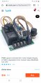
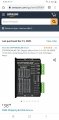
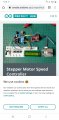
I need someone to build me a speed controller for a small stepper motor driver.
Needs to have remotely located start/stop, speed pot, reverse switch, and 3 place min digital display... More if possiple
Basically i need to panel mount the display and switches and speed pot, and have the control mounted elswere....
You can contact me via pm.
<Mods Note:
You can't post email on forum, it will bring the Spambot to you and forum>

Need asap
 

drc_567

Joined Dec 29, 2008
1,156
What is the actual load on the stepper motor? Is much torque required, or it is mostly a kinematic/motion application? What sort of application is it?
The stepper driver here does not require a microcontroller, just an adjustable clock circuit.
stepper controller
A digital rpm indicator can provide a numerical display.
 
Last edited:

Thread Starter

Rlbooms

Joined Jan 22, 2021
28
It is a small 2" square stepper (i believe 3 amp max draw) that has no real load....... Moving a welding gun for welding shaft diameters...... 250000 count per rev. And opperating at about 17 to 25 % speed.
I have the driver, power supply and motor..... but for osha requirements i need all the electronics in a box but all the controlls on the face of the box to adjust speeds and direction as each different job comes along
I am at home right now and stuff is at work so i dont have the spec here but it is a small light duty system...
I need to be able to see the % power or rpm numbers so that i can build a chart over time as to what diameter shaft uses what rpm on the stepper and on the motor driving the shaft..... (have that part already) to produce a nice even weld.
All on line speed controls have all the controlls hard mounted to the board... Saw one that showed building one but it was just a bit over my head..... And lots of pwm motor controlls built with remote mounted controls but i believe that they will not work for controllig a stepper driver
 

drc_567

Joined Dec 29, 2008
1,156
... Ok ... getting some idea of the project. It sounds like the parts need to be assembled and tested. Do you have a completed mechanism that works to your satisfaction? If not, what exactly is missing?
 

Thread Starter

Rlbooms

Joined Jan 22, 2021
28
... Ok ... getting some idea of the project. It sounds like the parts need to be assembled and tested. Do you have a completed mechanism that works to your satisfaction? If not, what exactly is missing?
Yes
I have a full system..... The stepper speed controller is an all in one and the display flickers to much.. (cheap china crap) see pic

I need to have that unit built but have all the control functiins be made to be remotely adjusted... Ie knobs on panel face and board located inside the electrical enclosure.... 16-24" away. Pict 2 is an example of what i am talking about.... But with a stepper motor control instead of a std motor controller
 

Attachments

drc_567

Joined Dec 29, 2008
1,156
... Specifically, do you have a means to control the stepper motor?
I listed a possible stepper driver in my first reply post.
That part has the capability to go forward, reverse, go to a home position, with simple on/off switching. All that is required is a clock pulse to the chip, which can be generated by an independent circuit.
... The measurement of the rotational shaft speed would require that some type of magnetic feature be installed on the motor shaft, so that an RPM reader could be used. Exactly how that could be accomplished in a suitable manner is yet to be determined. Possibly, the motor shaft could be magnetized by passing a DC current through a small spot that could be sensed by the RPM reader.
 

Thread Starter

Rlbooms

Joined Jan 22, 2021
28
Currently i have the speed control in the pic.., a stepper driver, and stepper motor.
All working..... It is not programable....... It would be nice to be able to hit a home button to reset the welding head to the start point...... Right now i just planned on reversing manually to run the head back to the start point.

I am not opposed to replacing the stepper driver with something else.... The syatem rpm is very low..... Only a couple rpm so shaft mointed rpm measure would be hard. Attached are the drive and motor used
 

Attachments

drc_567

Joined Dec 29, 2008
1,156
The DM542 controller that you have seems to be a fixed pulse rate controller that can only be adjusted by changing certain switch positions. ... What you require is variable speed adjustment, maybe with a knob or dial, and also a numerical readout of the shaft revolutions per minute.
... I'm not seeing an immediate way to do this with the DM542 controller.
... Another way to obtain accurate shaft speed measurement is with an encoder wheel. That would require an extra circuit.
 

shortbus

Joined Sep 30, 2009
10,045
The DM542 controller that you have seems to be a fixed pulse rate controller that can only be adjusted by changing certain switch positions. ...
No, that is one of the most common stepper drivers out there. It needs a astable square wave pulse to make it step. It needs the same thing the driver you linked to does. The switches on his are to select the amperage of the motor. Shown on page 9 of the PDF. dm542.pdf

The thing I don't understand is why the TS is using the linear stage he shows when he wants to make rotary motion? Or I assume since he said he is welding on a shaft.
 

drc_567

Joined Dec 29, 2008
1,156
... @shortbus ... Thanks for the clarification.
The task is to move a welding gun along a straight line at different speeds in order to achieve smooth, efficient welds. The rotational shaft speed is an indication of the linear weld gun speed.
... My DM542 manual download only came back with the first two pages.
 

MaxHeadRoom

Joined Jul 18, 2013
28,688
... PWM motor control is simply not compatible with stepper motors.
They are two different things.
Not strictly true.
Most modern stepper drives use PWM to control the constant mean level of current for the motor in question, the PS voltage is much higher than would be permissible to be used direct, it is higher to allow the rated motor current to be controlled at higher RPMs, as inductive reactance increases.
Max.
 
... PWM motor control is simply not compatible with stepper motors.
They are two different things.
PWM is used in stepper control, but for an entirely different reason, micostepping. The coils can have say 128 different values of current, thus they can step between full steps. the current can be controlled via PWM.
 

Thread Starter

Rlbooms

Joined Jan 22, 2021
28
So the switches are for setting motor amp and for pulses per rev.... 800 to 250000
The higher the # of pulses per rev the finer control and slower the motor turns.

The seperate speed adjuster has a speed pot and reverse and start stop switches and is meant to adjust the stepper motor rpm through the stepper motor driver.


I just need to get all the "control switches and speed pot". OFF the circuit board and remote mount them
See attached pic... This is what i found but am not comfortable to pull it off myself...
Using this board.... And method, i could remotely mount all the switches and speed pot
 

Attachments

drc_567

Joined Dec 29, 2008
1,156
One approach would be to draw a sketch of a control board that could be mounted inside the enclosure. It would be necessary to include the header and pin connections shown your picture.
At that point if everything is correct, it would be possible to contact a circuit board fabrication company, submit a drawing or an acceptable input and finally obtain a board to which the headers, pins, switches, and any other parts could be attached. The first step would be to come up with a drawing of the parts that are shown in the picture of your working assembly.
 

Thread Starter

Rlbooms

Joined Jan 22, 2021
28
Correct but i need someone who knows how it all works to make it......
Doesnt even need to be all that professional.... Just work...
I dont even mind the type board that is used in the picture...
 

shortbus

Joined Sep 30, 2009
10,045
Correct but i need someone who knows how it all works to make it...
The link to the stepper diver I gave shows the wiring. I'd personally use one of these for the step speed control -
https://www.ebay.com/itm/PWM-Pulse-...519504?hash=item446e131150:g:wIsAAOSwhJJf23Ra Set the duty cycle at 50% and leave it there, because the driver is expecting a square wave type pulse, 50% on - 50% off. Then use the frequency to control the speed. The reason for using one like that is that the digital display will be the same every time, where a potentiometer is kind of a guess for each speed. You would then need two more switches for the driver both of them single pole single throw. One for clockwise and counter clockwise. The other for start stop. Use that and keep the stepper drive on all the time using another switch.

All of that said, is Drc correct? Are you welding length ways on a shaft? Or is this for a type of positioner/turn table to weld a shaft into a gear or some other thing? Doing that is pretty common but building up a shaft to allow it to be remachined is usually done free hand, or it was any where I worked over the years.

So the switches are for setting motor amp and for pulses per rev.... 800 to 250000
The higher the # of pulses per rev the finer control and slower the motor turns.
You also don't want to use the micro steps if you don't have too. And those speeds sound like they are for micro stepping. Micro stepping is more prone to losing it's place and then the motor will just rock back and forth.

Another common mistake is using the wrong voltage. Even though the motor may say, 5V at 2 amps, the important thing is the 2 amps. And you set the dip switches for that. But Voltage is or should be much higher than the motor name plate voltage, like a minimum of 3 or 4 times higher or even more. Stepper motors are current motors and setting the dip switces sets the output of the driver. More volts makes the steps more secure, less prone to losing the progression.
 

shortbus

Joined Sep 30, 2009
10,045
The task is to move a welding gun along a straight line at different speeds in order to achieve smooth, efficient welds. The rotational shaft speed is an indication of the linear weld gun speed.
Doesn't make sense to me? I took it as he was making a turntable to weld around a gear or pulley or just a plate on to a shaft. Where the stepper controlled the speed of rotation and the weld torch stayed in one place.
Never saw it done like you say, but then I haven't seen everything I guess.
 

Thread Starter

Rlbooms

Joined Jan 22, 2021
28
The link to the stepper diver I gave shows the wiring. I'd personally use one of these for the step speed control -
https://www.ebay.com/itm/PWM-Pulse-...519504?hash=item446e131150:g:wIsAAOSwhJJf23Ra Set the duty cycle at 50% and leave it there, because the driver is expecting a square wave type pulse, 50% on - 50% off. Then use the frequency to control the speed. The reason for using one like that is that the digital display will be the same every time, where a potentiometer is kind of a guess for each speed. You would then need two more switches for the driver both of them single pole single throw. One for clockwise and counter clockwise. The other for start stop. Use that and keep the stepper drive on all the time using another switch.

All of that said, is Drc correct? Are you welding length ways on a shaft? Or is this for a type of positioner/turn table to weld a shaft into a gear or some other thing? Doing that is pretty common but building up a shaft to allow it to be remachined is usually done free hand, or it was any where I worked over the years.


You also don't want to use the micro steps if you don't have too. And those speeds sound like they are for micro stepping. Micro stepping is more prone to losing it's place and then the motor will just rock back and forth.

Another common mistake is using the wrong voltage. Even though the motor may say, 5V at 2 amps, the important thing is the 2 amps. And you set the dip switches for that. But Voltage is or should be much higher than the motor name plate voltage, like a minimum of 3 or 4 times higher or even more. Stepper motors are current motors and setting the dip switces sets the output of the driver. More volts makes the steps more secure, less prone to losing the progression.
So my system is this.... I have a 1/2 hp ac motor controlled by a variable speed ac drive, this motor is connected to a gearbox which turns a small 6" chuck.
You place a worn shaft into the chuck and tighten.
Turn the drive on and adjust the rotation speed with the ac drive.
Then using the linear stepper system (which holds my welding gun) you set the stepper motor speed to give a nice even stepover (spiral effect) of the welding gun on the shaft od. Then turn on welder and let it auto feed across the shaft length until you have covered the length of shaft you wanted welded. Then turn it in a lathe to finish repair. I deal with repairs all the time in my buisness Valley Gear & Machine inc., Bad Axe, MI
Tired of manually hilding the gun and less than perfect coverage with the welder

I tested the system and it works great... See pic.
But now need to make the control osha comoliante and have the user controlls easy to acess and use.

I really would like to pay some one to build the speed control and send it to me.
 

Attachments

Top