StepDown Transformer 220v ---> 120v " Frequency issue !"

Thread Starter

Abdelrhman_Hashem

Joined Sep 19, 2019
6
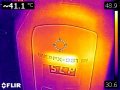
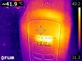
Recently I'm Receive " Hakko FX951 Solder Stations With This Spec ---> 120v/60Hz -- 75W " ... And My Country Have 220v/50Hz I'm Wondering If I bought StepDown Transformer from 220v/50 to 110v/50Hz Are This work Fine With This Solder Stations Or Not ?

Thank u For Attentions ..
 

ci139

Joined Jul 11, 2016
1,898
technically
the upper frequency the TF can handle is dependent on laminates thikness
the 50Hz causes slower flux change ...
... increasing (perhaps) requirement for the colis to handle current
i donno this subject ...
if the wire diameters used for 60Hz designs are thinner (due XL=2πfL *current limitting) -- it may have a temperature increase because of the wire/coil (linear) resistance . . .
. . . and thus resistance rize and thus reduced I/O Power -- more likely * just 20% higher current due lower frequency
((((it is also possible to design a heat sink for the TF -- but such might be a desk size for 75W /// ...×20% 15W (19W TF losses added) -- without fan and fins - a book size actually ))))

well it means you need to verify the issues as safe before proceeding
 
Last edited:

Thread Starter

Abdelrhman_Hashem

Joined Sep 19, 2019
6

Thread Starter

Abdelrhman_Hashem

Joined Sep 19, 2019
6
Today i'm Receive SIMRAN AC-500 " StepDown Transofrmer 220/110v 50Hz " 500 WATT " , After Connect Solder iron Hakko fx-951 120v/60Hz to Output 110 cord on StepDown Transformer, ---> I'm Actually Lazy Today to " Teardown Hakko Solder Station In Line "Under Operation " So :-
I'm Notice " By Using Flir C2 Thermal_Cam Focused Plastic Cover "Hard Plastic Case "In Solder Station" As In Image :-

- AFter 5 Minuites For continues Work soldering in Solder Stations --> 350 ْ c ( Not "SLP ---> Sleep Mode" ) The Tempreature Between " 32 - 36 " ْ c.

- After 1 Houre From Operation between SlP mode and Continues Work Soldering Tempreature Rise Between 50 - 55 ّ c

- In Slp Mode Tempreature 150 ْ c Decrease ~ 10 ْ c From Highest one;

I'm Think During Hard Work This Need To Modified By "Heat Sink" Attach Main Transformer Inside Hakko Solder Station
 

Attachments

jpanhalt

Joined Jan 18, 2008
11,087
Can you test it at 60 Hz? That is, 50°C is nothing, unless that is the outside temperature. I don't see a problem. Are you using the soldering iron to solder? Does it do that? If so, why worry?
 

Thread Starter

Abdelrhman_Hashem

Joined Sep 19, 2019
6
As a long shot, open it up and see what kind of source the 24v is, if a mains transformer, check to see if it has a primary voltage option, or if a SMPS, any detail on it.
As before, a long shot, but nothing to lose.
Max.
After Main Transformer " Linear One Primary and Secondary " , And Bridge Rectiver , Capacitors ---> 24v Dc Rail
 

Attachments

Thread Starter

Abdelrhman_Hashem

Joined Sep 19, 2019
6
Can you test it at 60 Hz? That is, 50°C is nothing, unless that is the outside temperature. I don't see a problem. Are you using the soldering iron to solder? Does it do that? If so, why worry?

- Test ---> 110v/50 Hz from outputing StepDown Transformer ,
My Qustion :-
--> Are 55 ْc " May be Temp Rise After Long Work " Save to Work Or Handle it Because I need Efficiency in Micro Soldering Iron ?
--> Save Work Space "No Blowing up " :) ?
 

ci139

Joined Jul 11, 2016
1,898
(-1-) this is much unlikely and hypothetical far shot . . . but if there is room in windings' windows then by increasing the average diameter of the coils would result in higher inductance ... and impedance ← that would somewhat limit the current /!\ but also change the magnetic coupling to core -- with unpredictable results . . . besides you'd need to increase both windings by the same factor

(-1a-) the right thing to do would be add 20% inductance to both coils by the same diameter wire . . .

(-1b-) it may be possible to add same laminates and make the TF more fat ... and make room for "extended" coils /// would be easier to make one from scratch . . . (i even thought once to add 2 cores to make 1 more powerful TF but hand-winding 6000 turns of delicate primary wire would be a nightmare ...) . . . leads to → ↓

option (-1c-) = buy 1 more TF and take some wire off both TF-s and both coils so that the TF's end up identical . . . connect the I-ries in series and the II-ries in series ? a month of lab . . . + there's no warranty that the wire can be unwound without breaking it or the insulation + the laminates need to be re insulated by lacquer . . . = mission impossible

but there might be a person or company that does such maybe with reasonable price . . .
_______________________

(-2-) by heat sinking you'd actually keep your current.. (otherwise a bit limited by the https://en.wikipedia.org/wiki/Temperature_coefficient) ..high ??? that would likely add to core temperature (by increased magnetic field) . . . e.g. "you'd overclock" your transformer keeping it in "abnormal" operating condition

it may work -- but it may and not be a good thing to try
 
Last edited:

jpanhalt

Joined Jan 18, 2008
11,087
- Test ---> 110v/50 Hz from outputing StepDown Transformer ,
My Qustion :-
--> Are 55 ْc " May be Temp Rise After Long Work " Save to Work Or Handle it Because I need Efficiency in Micro Soldering Iron ?
--> Save Work Space "No Blowing up " :) ?
You missed my point. Your thermal imaging shows a temperature at 50 Hz. What would the temperature be at 60Hz? Maybe its better; maybe worse by a little. Will it affect function?
 
Top