Steady DC current to Pulsating DC current

Thread Starter

sab201

Joined Nov 18, 2023
297
Good Day All,

I like to use a pulsating DC current output for an electromagnet and I like to know if it is possible.

Right now I have an electromagnet that is powered by a buck converter. The buck converter is supplied by a 12 Volt DC adapter. The output of the buck converter is 3.5 Amperes at 6.15 Volts.

I like to know if it is possible to pass a pulsating DC current of peak Value 3.5 Amperes and minimum 1.5 Amperes with variable frequency through the electromagnet.

I am studying the behaviour of magnetic fields through electromagnets and like to use pulsating DC current through the electromagnet. I do not want to use AC because that will constantly change the North South poles of the electromagnet.

Thanks
 

Ian0

Joined Aug 7, 2020
13,126
Good Day All,

I like to use a pulsating DC current output for an electromagnet and I like to know if it is possible.

Right now I have an electromagnet that is powered by a buck converter. The buck converter is supplied by a 12 Volt DC adapter. The output of the buck converter is 3.5 Amperes at 6.15 Volts.

I like to know if it is possible to pass a pulsating DC current of peak Value 3.5 Amperes and minimum 1.5 Amperes with variable frequency through the electromagnet.

I am studying the behaviour of magnetic fields through electromagnets and like to use pulsating DC current through the electromagnet. I do not want to use AC because that will constantly change the North South poles of the electromagnet.

Thanks
Not easily, as the inductance of the electromagnet will prevent any sudden changes in current.
You will only be able to do so a low frequencies. At higher frequencies, the current will be a triangle-wave.
 

Thread Starter

sab201

Joined Nov 18, 2023
297
The rate at which the current can increase or decrease depends on the applied voltage.
So, is it possible to connect a resistive load in series with the electromagnet. That is connecting a controller timer switch on off module in series that connects and disconnects a resistor in parallel to the switch based on timer so that the buck converter raises and lowers the output voltage.

I am not sure if this is right. That should depend upon the buck converter.
 

BobTPH

Joined Jun 5, 2013
11,503
So, is it possible to connect a resistive load in series with the electromagnet
That is not at all what I was getting at.

What I was trying to convey was that, in order to get a sharp increase in current, you may need a voltage far higher than that required to maintain a steady current.

A true mathematical square wave would require infinite voltage. Anything less gives you a current that rises over some amount of time, the higher the voltage, the faster the current rises.
 

ElectricSpidey

Joined Dec 2, 2017
3,326
You can do what you want with a 555 and a power transistor.

Then you bypass the transistor with a power resistor to set the lower current.

But as noted you will have to use lower frequencies.

And don't forget to suppress the back emf from the magnet, I would use at least a 5-amp diode.
 

AnalogKid

Joined Aug 1, 2013
12,117
I like to use a pulsating DC current output for an electromagnet and I like to know if it is possible.
Yes, this can be done. Your question is missing some important details.

For each on/off cycle, how long is the magnet to be on? How long is the magnet to be off?

What is your skill set for building a small circuit on perf-board? Are you familiar with the 555 IC?

ak
 

MisterBill2

Joined Jan 23, 2018
27,447
Certainly the DC supply voltage to an electromagnet can be pulsed. And the previous comments about rate of current change and correct. The limitations will depend on the pulse rate and the electromagnet's inductance.
A simple NPN power transistor connected common emitter, in the magnet return connection to the supply will work, but it may take a couple of stages of amplification to be able to switch the transistor on and off rapidly, given that the plan is to switch from full off to full on very rapidly.

But you do need to clarify the rate of pulsing and what the on and off times of the pulses need to be.
 

Thread Starter

sab201

Joined Nov 18, 2023
297
But you do need to clarify the rate of pulsing and what the on and off times of the pulses need to be.
sketch-1712032615087.jpg

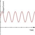
I like the waveform to be like this but not exactly it just need to be pulsed and it is better if the lowest value does not hit zero. The peak value must be 3.5 Amps and the lowest 1.5 Amps. Frequency could be of any value that is possible to achieve this pulsed output. But I am not sure if pulsing without hitting zero is possible with an ON/OFF switch or transistor.

Thanks
 

Thread Starter

sab201

Joined Nov 18, 2023
297


For each on/off cycle, how long is the magnet to be on? How long is the magnet to be off?

What is your skill set for building a small circuit on perf-board? Are you familiar with the 555 IC?

ak
The magnet will be on continuously only the DC current through the magnet has to be pulsed.

Well I have very low skill set on that you mentioned. I can use readymade modules and make circuits by reading their maker manuals.

Thanks!
 

MisterBill2

Joined Jan 23, 2018
27,447
OK, a sine wave can indeed be delivered with a similar output circuit but a quite different base drive signal. The efficiency would be rather poor, though. It would be what is well defined as a Class "A" single-ended amplifier.

But I would not call that a "pulsating" voltage. Some of us think of pulses as binary, either ON or OFF., or at least, spending a very small amount of time in the transition between two different levels. THAT is what has caused a bit of confusion, and resulted in suggestions that do not meet the intended requirements.

Really, this could be provided by a combination of two standard instruments: An externally programmable power supply and a function generator with a controllable offset feature.
 

Thread Starter

sab201

Joined Nov 18, 2023
297
Really, this could be provided by a combination of two standard instruments: An externally programmable power supply and a function generator with a controllable offset feature.
Well, that would run too expensive!

I was looking for a cheaper alternative possible.

Besides the waveform need not be an exact sinewave, it could also be rectangular. The idea is to send pulsed current continuously through the inductor to increase the magnetic field capacity or to see how it affects the magnetic field as compared with a normal steady dc current through the inductor.

Ofcourse a programmable power supply would be perfect but that is too inefficient for this application.

Thanks all for your responses.
 

MisterBill2

Joined Jan 23, 2018
27,447
Consider that an electromagnet's magnetic field variation is directly controlled by the current in the electromagnet, and that a magnetic field possesses no mass, the effect can be described by the math description of the current waveform. The external effects may be subject to residual magnetization of material within the field.

Given that magnetism and it's fields have been studied for a very long time, there is a great deal of published material available, with much of it being accurate.

Unfortunately there are also a fair amount of unverifiable claims about the effects of magnetic fields as well. Some of those have been published in "The Journal Of Unverifiable Results", an interesting publication that I came across a few years ago. IIt may still be available, possibly.
 

crutschow

Joined Mar 14, 2008
38,490
I have an electromagnet that is powered by a buck converter.
.................................
pass a pulsating DC current of peak Value 3.5 Amperes and minimum 1.5 Amperes with variable frequency through the electromagnet.
It should be possible to add a varying voltage from a signal generator into the buck converter's feedback loop to also vary the output voltage
What buck converter are you using, and can you post a schematic of its circuit?
 

AnalogKid

Joined Aug 1, 2013
12,117
When you said "pulsing" in the title and post #1, *everyone* thought you wanted to drive the magnet with some form of square wave. The waveform in post #8 is more difficult.

One thought is an audio power amplifier but without the output coupling capacitor, driven by the earphone jack of a phone of pc playing an audio tone app. But you need to be specific about frequencies. There are a lot of options between 0.0000116 Hz (once per day) and 1,000,000 Hz (where things start to get very radio-ish). Pick some. No numbers, no real answers.

ak
 
Last edited:

BobTPH

Joined Jun 5, 2013
11,503
Depending on the voltage, frequency, and the inductance of the coil, that waveform might have very little effect on the current in the magnet.

So what are the above mentioned parameters?
 

Thread Starter

sab201

Joined Nov 18, 2023
297
It should be possible to add a varying voltage from a signal generator into the buck converter's feedback loop to also vary the output voltage
What buck converter are you using, and can you post a schematic of its circuit?
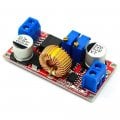
This is the buck converter details

https://roboticsdna.in/product/5a-c...ery-charging-module/?src=google&kwd=&adgroup=

XL4015E1 CONSTANT CURRENT/VOLTAGE 5A LITHIUM CHARGER DC-DC STEP DOWN ADJUSTABLE MODULE INPUT 5V-32V OUTPUT 0.8V -30V

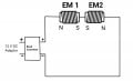
XL4015E1-CONSTANT-CURRENTVOLTAGE-5A-LITHIUM-CHARGER-DC-DC-STEP-DOWN-ADJUSTABLE-MODULE-INPUT-5V...jpgHere is the schematic of the circuit. Its simple, consists of two electromagnets in series separated in space with winding done appropriately to create north and south poles.

sketch-1712068269042~2.jpg
 

Thread Starter

sab201

Joined Nov 18, 2023
297
When you said "pulsing" in the title and post #1, *everyone* thought you wanted to drive the magnet with some form of square wave. The waveform in post #8 is more difficult.
Yes I admit I caused a confusion there however I mentioned *not exactly* meaning it need not be an exact sinewave. You are right pulsating stands for square waves. In my case it does not matter it is sine or square wave as long as it is possible to produce that.

Edit: Whichever waveform and the corresponding method is feasible and cost effective and efficient.
 
Last edited:

crutschow

Joined Mar 14, 2008
38,490
This is the buck converter details
You can try inputting a signal from a signal generator to the wiper pin of the voltage control pot through a large capacitor (e.g. ≥100uµF).
The upper frequency limit will be determined by the response time of the converter.

Edit: You may have to add a resistor (start with 1kΩ) in series with the capacitor so the output doesn't oscillate.
 
Last edited:
Top