 Facebook
 Google
 GitHub
 Linkedin
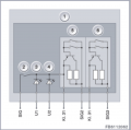
I am trying to install separate switch after this one (attached screenshot - this is standard start-stop button for the ignition) that will cut the ignition curcuit.
As far as I understand if I cut SIG2 and SIG3 pinout/wires and install on/off switch, computer of the car will probably log this as an error (because it will look like broken curcuit/switch). In order to avoid that I am looking for solutions, basically as we can see from the schematic, when button is in open state some resistance is applied, and when button is pressed, resistance should be less because of the parallel connection between the wires. The question is what element should I put after SIG2 and SIG3 in order to keep the resistance the same all the time, no matter whether button is pushed or not. That way button will just not function (even if I push it - which is my goal) and car computer will not log any error.
Please correct me if I am wrong , but I imagine that by default there is 3V and after pressing button voltage is 5V, which represents 0 and 1.
In order to keep voltage 3V always (when enabled by the separate switch), can I add zener diode after SEG2 and SEG3 to make the voltage be always 3V or I need to do something more advanced?
Attachments
-
 462.8 KB Views: 22
 -
 226.2 KB Views: 20
Last edited:


