 Facebook
 Google
 GitHub
 Linkedin
Hi,
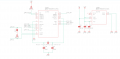
As per title, the MCP25625, which is a CAN transceiver commanded over an SPI interface, it's not responding to any commands received over SPI. I'm trying to send a simple 'READ' (0x03) command to the device and get the contents of the CANCTRL register (0x0F). I even moved past our project board and bought Microchip's development board for the MCP25625 to rule out any weird HW design issue. In both cases I've measured the CLKOUT pin using my oscilloscope and it's correctly reading 2.5MHz (20MHz crystal / 8 default prescaler), suggesting that the chip it's clocked correctly and, presumably (datasheet is unclear about this), alive and working.
The only odd thing about both my setups is that I'm powering VDD from 3V3 and Vdda from 5V.
SPI MISO is pulled high using a 10K resistor to 3V3. SPI is running in mode 0,0 with data valid on the clock's leading edge, as per the picture attached. I tried everything so far:
1. Disconnected the MISO line from the MCU. Tried both pulling it up and leaving it floating. Same result (0xFF when it's pulled up, 0x00 when it's left floating).
2. Tried all SPI modes.
I'm genuinely out of ideas, the SPI data looks correct, but the chip isn't replying at all.
Happy to try anything at this point and thanks for any idea you throw at me, no matter how crazy it might sound!
Attachments
-
 21.4 KB Views: 14
 -
 5.6 KB Views: 10
 -
 39.9 KB Views: 8

")


