Source Transformation

Thread Starter

Ponyboy

Joined Jan 26, 2014
6
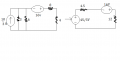
So I only need help on p5.2.2. I am confused on the how to orient a source after you transform. In p5.2.2 the current source on the top is going to be transformed into a voltage source, but where do the polarities go. In the end I got 2 answer 2/3 and 46/21 putting the polarities in different directions. if some one could explain this question that would be great!!
 

WBahn

Joined Mar 31, 2012
33,192
Your figure did not post correctly.

When you transform a source, just remember that it has to behave equivalently (in terms of voltage and current at the terminals) to what it is replacing. So orient it so that it does this. For this purpose, ignore all of the other components and just look at the components being transformed before and after the transformation.
 

Thread Starter

Ponyboy

Joined Jan 26, 2014
6
I only need help on the first question p5.2.2 I got two answer and I want to see if either of those answer are correct, 2/3 or 46/21. I don't know which of my orientations are correct. Thanks
 

WBahn

Joined Mar 31, 2012
33,192
I only need help on the first question p5.2.2 I got two answer and I want to see if either of those answer are correct, 2/3 or 46/21. I don't know which of my orientations are correct. Thanks
Have you tried checking your answer to see if it is correct? Assume that the 2/3 A (and note that 2/3 is not a current, but 2/3 A is) is correct and walk it through to see if the circuit is consistent with that. If not, then check 46/21 A and see if it is.

Alternatively, there are several other ways to solve the problem. Node voltage analysis, mesh current analysis, and superposition are but three of them.

You need to start applying the practice of checking your own work, because in the real world you seldom can go ask someone if your answer is right. The reason is simple: if someone else knew the answer, they wouldn't have hired you to solve the problem in the first place.
 
when I apply source I get a schematic that looks like the picture I posted below. But I source transformed multiple times,ex.The 10V source in series can be transformed into a 10/3A source with a 3 ohm resistor in parallel.And then the 3 ohm and 6 ohm resistor are in parallel,which can be combined.After combining,apply another source transform to get 45/3V source in series with a 4.5 ohm resistor.I also source transformed the 2A source in parallel with the 8 ohm resistor multiple times.

When trying to label the polarities take notice of either the + and - or the way the arrow points, normally with a source the polarity goes from low(-) to high(+).

But take my thoughts with a grain of salt,as I am new as well to analysis techniques.I myself prefer either superposition or mesh.
 

Attachments

shteii01

Joined Feb 19, 2010
4,644
when I apply source I get a schematic that looks like the picture I posted below. But I source transformed multiple times,ex.The 10V source in series can be transformed into a 10/3A source with a 3 ohm resistor in parallel.And then the 3 ohm and 6 ohm resistor are in parallel,which can be combined.After combining,apply another source transform to get 45/3V source in series with a 4.5 ohm resistor.I also source transformed the 2A source in parallel with the 8 ohm resistor multiple times.

When trying to label the polarities take notice of either the + and - or the way the arrow points, normally with a source the polarity goes from low(-) to high(+).

But take my thoughts with a grain of salt,as I am new as well to analysis techniques.I myself prefer either superposition or mesh.
Basically, the terminal from which current is leaving the source is the positive terminal. Terminal at which current is entering the source is the negative terminal. It seems to me that you labeled the voltage terminals correctly.
 
Top