SONAR - received signal and filter issues

Thread Starter

paltanuoto

Joined Jul 5, 2025
8
Hi guys, I need your help! It's my first time building electronic circuits and I'm really struggling as I'm a total noob when it comes to electronics.

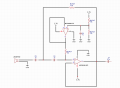
I'm building a SONAR and I'm using an Arduino Due (mainly due to its higher ADC speed, as the sonar works at 25kHz). I've checked the entire transmission line and I'm sure that everything there works fine.

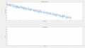
Analyzing the receiving line, though, I noticed a couple of strange things. Since I don't have an oscilloscope, I'm using the analog pin of my Arduino to check the signal. I transmit a continuous 25 kHz wave for the debugging. When I read the raw input from the receiver (detaching all the circuit that follows the receiver), I see a signal that decreases in steps, and I don't understand why.

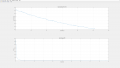
Furthermore, after filtering it with a Sallen-Key filter (high-pass with cut -off frequency at 20 kHz), I still see a decaying trend in the output while ideally i expect a signal centered in 0 and filtered.

My question is: do you have any clue why I don't simply receive a 25kHz wave (with some noise, obviously) and why my filter doesn't seem to work?

I'd be really grateful for any help!!!
 

Attachments

ericgibbs

Joined Jan 29, 2010
21,423
hi pal,
Welcome to AAC.
This is what LTSpice shows, for the BW please check my circuit copy for accuracy.

E
Corrected an error,
I have used an equivalent OPA type.

EG 1595.png
 
Last edited:

ericgibbs

Joined Jan 29, 2010
21,423
What sort of sonar uses a constant signal?? That is not realistic for an actual system. Real sonar does not work that way!!
hi Bill,
If that post was directed at me, I would say you don't have a clue what you are talking about.

E
 

Thread Starter

paltanuoto

Joined Jul 5, 2025
8
Hi pal,
What level of Gain are you expecting from that circuit,? and also why not a band pass filter?
E

View attachment 352280
Hi, I started with a high-pass filter to simplify the design. I expect only a small attenuation from the filter, because it is followed by an amplifier with a gain of 25 (linear scale) that does all the amplifying work. However, Google Gemini identifies a critical instability in the amplifier stage (the transimpedance amplifier). It seems that the large intrinsic capacitance of the ultrasonic transducer (the 250SR160, which is around 2.4 nF ) interacts with the feedback resistor (R1_FILT), and so I should use a compensation capacitor in parallel with that resistor. Without it, the amplifier becomes unstable and its output saturates, which is why I see that strange descending waveform instead of the 25 kHz signal.
 

Thread Starter

paltanuoto

Joined Jul 5, 2025
8
Welcome to AAC.

This sounds like a capstone project. Are you receiving a grade or academic credit for this work?
Welcome to AAC.

This sounds like a capstone project. Are you receiving a grade or academic credit for this work?
It is a free-choice project for a signal processing exams. Usually we simulate the received signal directly in MatLab but i exaggerated a bit deciding to build a real sonar.
 

MisterBill2

Joined Jan 23, 2018
27,384
as mentioned, it was just for debugging, just to check if the circuit correctly processes the wave
ALL of the sonar packages that I have seen sent out pulses and measured the time for the reflection to return. So the pulse sources never delivered a constant signal.
There is a "pseudo-doppler" scheme that uses a swept frequency and compares the returned frequency to the transmitted frequency. That has been used for many decades.
Pulsed signal echoes do not generally start and end instantly, at least not at any serious distance relative to a single wavelength. And certainly receive detector circuits are not instant either.
 
Last edited:

MrChips

Joined Oct 2, 2009
34,719
For sonar, you don't need to digitize the received signal.
All you need to do is measure the time interval between the first rising edge of the transmitted and received signals.
 

Thread Starter

paltanuoto

Joined Jul 5, 2025
8
Hi, I started with a high-pass filter to simplify the design. I expect only a small attenuation from the filter, because it is followed by an amplifier with a gain of 25 (linear scale) that does all the amplifying work. However, Google Gemini identifies a critical instability in the amplifier stage (the transimpedance amplifier). It seems that the large intrinsic capacitance of the ultrasonic transducer (the 250SR160, which is around 2.4 nF ) interacts with the feedback resistor (R1_FILT), and so I should use a compensation capacitor in parallel with that resistor. Without it, the amplifier becomes unstable and its output saturates, which is why I see that strange descending waveform instead of the 25 kHz signal.
Of course it just a chatbot and i'm not good enough to understand if it's right. It doesn't even understand that one of the two op-amps is a voltage follower. Anyway it remains strange the first graph that goes down not even linearly. Maybe it could be the fact that the transducer produces a current and not a voltage and it is not right to measure it with the analog reader of arduino.
 

Thread Starter

paltanuoto

Joined Jul 5, 2025
8
ALL of the sonar packages that I have seen sent out pulses and measured the time for the reflection to return. So the pulse sources never delivered a constant signal.
i do not deliver a constant signal to measure the distances. I deliver a continuous wave just to be sure that the receiving circuit works as it should, processing the signal correctly. Once debugged the circuit, i will proceed sending pulses and measuring the delay with cross correlation on Matlab.
 

Thread Starter

paltanuoto

Joined Jul 5, 2025
8
For sonar, you don't need to digitize the received signal.
All you need to do is measure the time interval between the first rising edge of the transmitted and received signals.
that's true but it is for an exams in which we studied digital signal processing, so the idea is to have the rouge measures of the receiver and then process it on my laptop.
 

nsaspook

Joined Aug 27, 2009
16,276
Top