someone can edit one gerber file for me?

Thread Starter

Mullins

Joined Dec 31, 2021
168
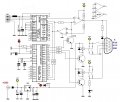
Please is there someone who can remove a rectangle from an greber file? i Download one project from internet but the pcb producer (xxxpcb) cant print it. I need an free software or someone who can do it. There is an big rectangle to remove. thank you so much.
 

Attachments

BobTPH

Joined Jun 5, 2013
8,809
Gerber files are text files. You can edit them with any text editor. Look up the Gerber file format to see what command creates a rectangle then search for it in your Gerber fike.
 

Thread Starter

Mullins

Joined Dec 31, 2021
168
Thank you Bob. it'a a great idea but I'm not able to do that. And now I have another problem. The website where I ordered this pcb is asking me "drill file". I renew my request for this too. Please can someone help me with this file? I can't create it. Please do it for me.
Thank you very much
 

Irving

Joined Jan 30, 2016
3,843
I had a quick look at your files, the big rectangle appears in most of them. What I don't see is a drilling file, yet you have a number of THT parts? I tried uploading the files to my preferred PCB supplier. There are a number of issues, including:
  • no drilling file;
  • front silk-screen extends outside the board area.
  • a number of thru-holes have no copper on the back of the board (eg USB connector etc.)
  • there's a diode (bottom right, below connector) with no connect to cathode
Creating a drill file just from the Gerber files isn't easy and will be time-consuming; I can't help you there. Where did you download these from?

1668162990836.png
 

BobTPH

Joined Jun 5, 2013
8,809
If there is no copper on the bottom, perhaps it is intended to solder the THT parts on the top.

It also looks like there is an SMT part under the largest IC, which isn’t going to work out so well.
 

Thread Starter

Mullins

Joined Dec 31, 2021
168
This is the circuit of the pcb. This project is all over the Internet. This must be an interface for "k-Line" to diagnose the car. If I agree to produce it without holes, can I make them in the future? Do you know of an intuitive (free) program that I can use to do this project again?
 

Attachments

Jon Chandler

Joined Jun 12, 2008
1,029
The easiest method would be to lay out a new pcb, either starting from the schematic or carefully following the existing board. Trying to create a drill file from the existing board would be extremely tedious at best.

I recommend using EasyEDA that's provided by JLCPCB. It has a short learning curve, massive component libraries, and they don't hold your Gerber files hostage – one click and you have a complete ZIP file that any fab house can build.

JLC also offers an incredibly cheap assembly service. The service is nearly free but you pay for the components and the assemble ten boards. The fine print:

● They only use parts in their system (a huge array)

● Commonly used parts are "basic" ‐ you only pay the component cost

● Other parts are "extended" - there's a $3 one-time up charge for these components ($3 to load the pick&place machine, whether you have one per board or a hundred).

● The default quantity of assembled boards is ten. If you only want them to make two or three or whatever, you'll pay the same or more than the cost to make 10.
 

Jon Chandler

Joined Jun 12, 2008
1,029
If you are going to use JLC's assembly service, it's highly recommended to use EasyEDA. It's easier to choose parts in the assembly system and to create the needed BOM (Bill Of Materials) and centroid files in their format.
 

panic mode

Joined Oct 10, 2011
2,715
this is a one layer PCB designed for types that can etch their own board and then drill the holes yourselves.
and that is fine if you have all exact parts from the list (all with with correct package, relay and connectors for example). otherwise design own PCB.
 

Jon Chandler

Joined Jun 12, 2008
1,029
First off, I don't believe this board was intended for home brew. Notice the fine pitch IC with traces between the pads. Good luckassembling the board without soldermask.

If you don't have the stuff to make your own board, it's going to be much cheaper to have 10 boards fabbed in China, even with postage.

10 boards, 100mm × 100mm or smaller: $5
DHL shipping: $25? (haven't checked recently)

Total: $30 for 10 copies (or slightly less for 5 copies)


For a home built board, if you don't have the necessary materials, tools and supplies, it's going to get costly. If you've never etched a board before it will probably take several tries to get a working board, particularly with fine-pitch parts with traces run between pads. And good luck trying to solder those fine pitch parts with traces between the pads.
 

Thread Starter

Mullins

Joined Dec 31, 2021
168
Irving
do you think the schematic is ok or even this have some problem?

"And good luck trying to solder those fine pitch parts with traces between the pads". Unfortunately for me the problem is all the rest :(, I'm very able to rework pcb with tsspo, lqfp...
 

Jon Chandler

Joined Jun 12, 2008
1,029
If you're reworking commercial boards they have soldermask. On a homemade board without soldermask, it would be difficult to avoid solder bridges to the tracks or even pad to pad.

I, like many people, am reluctant to open rar files, and you've never said what this "all over internet" board does, so who knows if the schematic is correct.
 

Thread Starter

Mullins

Joined Dec 31, 2021
168
Irving
opened my .RAR and nothing happened. You can even try to open it with some online viewer. This circuit is an interface between pc and car ECU (electronic control board)
 

panic mode

Joined Oct 10, 2011
2,715
If you're reworking commercial boards they have soldermask. On a homemade board without soldermask, it would be difficult to avoid solder bridges to the tracks or even pad to pad.
absolutely correct but the this is ok for one off projects. this seem to be diagnostics interface for some car. so one board is enough even if one decides to start business repairing that type of a car.

I, like many people, am reluctant to open rar files, and you've never said what this "all over internet" board does, so who knows if the schematic is correct.
this is one of many variants of ODB interfaces. K-line interface is a simple level shifter. there are others that do not need programmed chip. and getting PIC16 is going to be hard or expensive
 
Last edited:

panic mode

Joined Oct 10, 2011
2,715
btw, TS did not show which specific rectangle is the problem. i see several of them.

there is also plenty of options to view gerber files - even without installing some EDA product. among free ones KiCad seem to be very popular but may need few tweaks if you want to want to order assembled boards from someone like JLC
 

Irving

Joined Jan 30, 2016
3,843
Irving
do you think the schematic is ok or even this have some problem?

"And good luck trying to solder those fine pitch parts with traces between the pads". Unfortunately for me the problem is all the rest :(, I'm very able to rework pcb with tsspo, lqfp...
Looks OK, but do you have source code & progammer for the PIC? You can pick up a ready-made interface on ebay or Amazon for 20GBP/22USD. It'll cost a lot more than that to make one, plus a lot of hassle.


Irving
opened my .RAR and nothing happened. You can even try to open it with some online viewer. This circuit is an interface between pc and car ECU (electronic control board)
I always open files from unknown sources in a locked-down Windows XP virtual machine. Takes but a couple of seconds to start one up!
 
Top