(Solved) Loosely Coupled circuits, find Thevenin equivalent. Is my solution correct?

Thread Starter

babaliaris

Joined Nov 19, 2019
160
IMG_20201022_130117.jpg

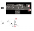
The j10 and j5 inductors are loosely coupled with M=j7. My professor told me to solve it using the T equivalent where the left inductor should be
j10 - j7 if the dots are next to each other, else j10 + j7 if the one is up and the other down. The same thing about the right inductor.
The dots are next to each other so left inductor becomes j10-j7 = j3 and the right inductor j5-j7 = -j2 .
 

Thread Starter

babaliaris

Joined Nov 19, 2019
160
I also tried to solve it using the mesh current method without transforming it to the T 4 poll equivalent. Take a look:
IMG_20201022_180811.jpg
 

MrAl

Joined Jun 17, 2014
11,389
Hello again,

I went back to your original drawing to check out the transformation from the two coupled inductors to the T model transformer.

Question: Are you sure you did this transformation correctly? I ask because i have to wonder how you got a 4 Ohm resistor in series with j7 where j7 is the mutual inductance.

Take a look at the attachment.
Transform circuit [1] then try [2].
Note the circuit drawn in [2] looks more clear on what we have to do.
You dont have to actually calculate anything just transform the circuits into the T equivalents.
 

Attachments

Last edited:

Thread Starter

babaliaris

Joined Nov 19, 2019
160
I'm positive I did it the wrong way... I know that because the dots are next to each other I can calculate the left inductor of the T equivalent using: L1-M and the right inductor: L2-M but I don't know how to re-draw the T equivalent and connect it with the rest of the circuit. This is what I have done wrong. I mean the T equivalent should have 3 inductors with the M inductor in the middle. But then how do I connect (re-draw) the circuit by using that T equivalent. Where is the left side of T is connected, where is the right side and where does the bottom side is connected to the rest of the circuit?
 
Last edited:

MrAl

Joined Jun 17, 2014
11,389
I'm positive I did it the wrong way... I know that because the dots are next to each other I can calculate the left inductor of the T equivalent using: L1-M and the right inductor: L2-M but I don't know how to re-draw the T equivalent and connect it with the rest of the circuit. This is what I have done wrong. I mean the T equivalent should have 3 inductors with the M inductor in the middle. But then how do I connect (re-draw) the circuit by using that T equivalent. Where is the left side of T is connected, where is the right side and where does the bottom side is connected to the rest of the circuit?
Hi,

That's why i was hoping you would look at the new drawing i provided in [2] because then the replacement set of inductors is much easier to visualize.
The left dot is the left side of the left inductor L1-M, the right dot is the right side of the right inductor L2-M, and the mutual inductor connects to the center connection the same way the original drawing [2] shows (or even your first diagram) the center connection and then the other end of the mutual inductor is the lower end of that inductor. That forms the "T".
You can then analyze the circuit as if they were still all inductors as long as you get the sign right unless you really want to replace the negative one with a cap, but that detracts a little from the graphical depiction of the T.
It is a good idea to think about why i drew the circuit over and notice the source ended up being upside down, but the more important point is that the two original inductors of the transformer are drawn right next to each other like that with both dots on top, and that makes visualizing the T form a lot easier.
 

Thread Starter

babaliaris

Joined Nov 19, 2019
160
I tried to do it again, this time trying to figure out how to connect the T with the rest of the circuit. I still got a wrong answer though. But this time, I named the joins to show you how I connected it. Maybe this time you can see exactly what I'm thinking wrong. Thank you so much for trying to make me understand!

IMG_20201023_175828.jpg

By the way I forgot the 4Ω under the capacitor but still this leads me to a wrong answer.
 

Attachments

Last edited:

MrAl

Joined Jun 17, 2014
11,389
I tried to do it again, this time trying to figure out how to connect the T with the rest of the circuit. I still got a wrong answer though. But this time, I named the joins to show you how I connected it. Maybe this time you can see exactly what I'm thinking wrong. Thank you so much for trying to make me understand!

View attachment 220402

By the way I forgot the 4Ω under the capacitor but still this leads me to a wrong answer.
Hello again,

It looks like you did the transformation drawing very well this time.

It is always a good idea to draw the circuit out completely before attempting to write the equations. In this example you remembered the 4 later but never included it in the new schematic and then when you went to write out the equations you forgot to include it in the calculation for Vth as well :)

Try again, this time remember to include the 4 Ohms in the equation calculations. You should then be able to get the right answer.

When doing circuit analysis problems we have to be very very careful and sometimes have to do it all over again because it becomes obvious that something wasnt right yet. The best graphical representation will help reduce errors later and it is surprising how much that helps.
 

Attachments

Thread Starter

babaliaris

Joined Nov 19, 2019
160
I think I made it!!!

Using T Equivelent:


Without it:


By the way, I had my calculator in Radians mode and got the angles wrong. Well, in this example because
|Vs|<0 had 0, the answer is still correct in Radians.
 

MrAl

Joined Jun 17, 2014
11,389
I think I made it!!!

Using T Equivelent:


Without it:


By the way, I had my calculator in Radians mode and got the angles wrong. Well, in this example because
|Vs|<0 had 0, the answer is still correct in Radians.
Just one question then. How is it that i am not seeing Vs/(1.5+j) anywhere?
 

Thread Starter

babaliaris

Joined Nov 19, 2019
160
Just one question then. How is it that i am not seeing Vs/(1.5+j) anywhere?
I'm not sure... Maybe I copied the wrong answer when I was keeping notes in the lecture. But I don't think I made any mistakes... If you spot any, please tell me!

Since I concluded in the same answer with both solutions, then it's really unlikely I did something wrong.
 

MrAl

Joined Jun 17, 2014
11,389
I'm not sure... Maybe I copied the wrong answer when I was keeping notes in the lecture. But I don't think I made any mistakes... If you spot any, please tell me!

Since I concluded in the same answer with both solutions, then it's really unlikely I did something wrong.
Well i mentioned that because i got the exact same result they did which was:
Vs/(1.5+j)

so of course i believe that to be correct. We could test with a simulation if you like.

Oh i see what you did, you did not strive to get the exact result you were happy with an approximate result. So in that case:
0.55470019622523 at angle -0.58800260354757 rads or
at angle -33.69006752597979 degrees

so now we get into rounding to two significant figures and i get:
0.55 at angle 0.59 rads
which is almost the same as yours except when i reduce to 2 digits i go to the third digit to use for rounding the 0.588.

So if you are happy with any of the results then you are done with this problem but feel free to comment if you like.
 
Last edited:
Top