Facebook
 Google
 GitHub
 Linkedin
hi g,
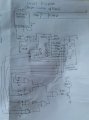
The 4026 and 4093 are CMOS IC's and the 7408 is TTL, you should not use CMOS and TTL logic together.
E
Look at this Link
https://www.allaboutcircuits.com/textbook/digital/chpt-3/logic-signal-voltage-levels/

The 4026 and 4093 are CMOS IC's and the 7408 is TTL, you should not use CMOS and TTL logic together.
E
Look at this Link
https://www.allaboutcircuits.com/textbook/digital/chpt-3/logic-signal-voltage-levels/
 ( as I've mentioned this was barely taught to us