Facebook
 Google
 GitHub
 Linkedin
Remember how I have repeatedly tried to get you to check both your results and the sim results to see if they are consistent with the original problem?
So let's do that for the sim results.
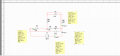
What is the control current 'i' in the original circuit? It's the current flowing right to left in the 3 Ω resistor? Right?
So what is it?
The voltage on the right of the resistor (Probe 1) is 0V. The voltage on the left of the resistor (ground) is 0 V.
So what is the current flowing through the resistor? ZERO!!!!
That means that the voltage across the depended source must be 0 V.
Is it?
Probe 4 = -155 V
Proble 3 = 2 V
So the voltage across the dependent source is 157 V.
Do you see the big red warning flag going up that something is wrong with your simulation??????
This would require that the current in the 3 Ω resistor is -17.44 A, which would require that the voltage at Probe 1 be -52.3 V, but your simulation says that it is 0 V.
Perhaps you might want to take a closer look at your simulation circuit compared to the problem circuit.
Here's a hint (again):
In the original circuit, the current that is controlling the dependent source is the current going THROUGH the 3 Ω resistor, right?
In your Multisim simulation, is the current that is controlling the dependent source going THROUGH the 3 Ω resistor?
So let's do that for the sim results.
What is the control current 'i' in the original circuit? It's the current flowing right to left in the 3 Ω resistor? Right?
So what is it?
The voltage on the right of the resistor (Probe 1) is 0V. The voltage on the left of the resistor (ground) is 0 V.
So what is the current flowing through the resistor? ZERO!!!!
That means that the voltage across the depended source must be 0 V.
Is it?
Probe 4 = -155 V
Proble 3 = 2 V
So the voltage across the dependent source is 157 V.
Do you see the big red warning flag going up that something is wrong with your simulation??????
This would require that the current in the 3 Ω resistor is -17.44 A, which would require that the voltage at Probe 1 be -52.3 V, but your simulation says that it is 0 V.
Perhaps you might want to take a closer look at your simulation circuit compared to the problem circuit.
Here's a hint (again):
In the original circuit, the current that is controlling the dependent source is the current going THROUGH the 3 Ω resistor, right?
In your Multisim simulation, is the current that is controlling the dependent source going THROUGH the 3 Ω resistor?