solid-state switch DPST with two triacs

Thread Starter

ebeowulf17

Joined Aug 12, 2014
3,307
This new circuit idea is partially an offshoot from my previous discussion:
http://forum.allaboutcircuits.com/t...aling-with-voltage-spikes.100777/#post-760288

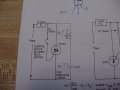
We have carbonator pump motors (240VAC, 1/3HP, ~2amps when running) in our machines that we currently switch with DPDT relays, except for machines being produced for Australia, where we use SSRs that are only switching one leg. We'd like to go solid-state on all machines to get away from noise issues that seem to be coming from the relay (arcing issues, maybe?) but for the US market, both legs have to be switched and 2 SSRs per motor gets bulky and expensive.

I have an idea for a simple circuit to switch both legs with triacs. I found the Littelfuse Q6040K7TP (manufacturer's docs here) which claims not to require a snubber circuit, even with highly inductive loads. It seems too good to be true, but it looks like with two triacs and two properly sized resistors, I can do what two big SSRs do, for less cost than a single SSR.

dual-triac_01.jpg

Am I missing something here? Is this basic idea sound? If so, any advice on modifications that would make it better? I'm very new at all this - getting better at picking out concepts but have so much to learn on all the specifics!

Assuming I've got the idea right, the resistors need to be sized to deliver more than the minimum gate current (100mA) and less than the absolute max (4A). I'm assuming it's better to stay near the low end, so maybe ~1200 ohms which would deliver 200mA @240VAC, meaning 48 watts that each resistor has to handle.

Thanks in advance!
 

inwo

Joined Nov 7, 2013
2,419
I have doubts that this circuit would commutate properly.

Could you use a standard triac static switch circuit from DP relay contacts?

ie. 200 ohm from MT2 to gate.

I've had good luck using alternistors (triac) switching solenoid loads with no snubber.
Use to extend contact life of PLC.
 

#12

Joined Nov 30, 2010
18,224
First, I'm not the guy to do the finished product. Reliability is part of this.
Second, look at a zero crossing opto isolator with a triac driver. That should help with the 100 watt resistors you were going to need.
Third, I have read about the circumstances when a, "snubberless" triac isn't.
4th, you should use a tiny transformer or something to make a low voltage to fire the opto with. Coming straight off the power line to a gate is asking for trouble from things like lightning surges.
 

Attachments

Johann

Joined Nov 27, 2006
190
This new circuit idea is partially an offshoot from my previous discussion:
http://forum.allaboutcircuits.com/t...aling-with-voltage-spikes.100777/#post-760288


I have an idea for a simple circuit to switch both legs with triacs. I found the Littelfuse Q6040K7TP (manufacturer's docs here) which claims not to require a snubber circuit, even with highly inductive loads. It seems too good to be true, but it looks like with two triacs and two properly sized resistors, I can do what two big SSRs do, for less cost than a single SSR.

View attachment 72644

Am I missing something here? Is this basic idea sound? If so, any advice on modifications that would make it better? I'm very new at all this - getting better at picking out concepts but have so much to learn on all the specifics!

Assuming I've got the idea right, the resistors need to be sized to deliver more than the minimum gate current (100mA) and less than the absolute max (4A). I'm assuming it's better to stay near the low end, so maybe ~1200 ohms which would deliver 200mA @240VAC, meaning 48 watts that each resistor has to handle.

Thanks in advance!
Look closely to your circuit:The only thing connected to the MT2 of either triac, is the motor. No potential difference between MT2 and MT1. The triacs won't turn on at all.
 

Thread Starter

ebeowulf17

Joined Aug 12, 2014
3,307
Look closely to your circuit:The only thing connected to the MT2 of either triac, is the motor. No potential difference between MT2 and MT1. The triacs won't turn on at all.
Unless I'm all turned around, it's the current running between MT1 and the gate that activates the triac (not MT1 to MT2.) The triac on the left will have voltage and proportional current flow through the gate as soon as the switch is closed. Activating the left triac will allow L2 voltage/current to flow through R2 into the right triac's gate. Since the right triac's MT1 is on L1, the L1/L2 power across MT1 and gate will activate the second triac, at which point each triac will provide a different AC leg to the motor, which should then be activated. I don't see how this could be described as no potential difference or triacs not turning on. Please correct me if I'm wrong on this.

...having said all that, there are several other problems that have been pointed out above. Even if my idea is theoretically correct, it needs a lot of work to be useful/safe in the real world. I'm going to look at redesigning it and see if this becomes a bigger project than we can justify, which is probably the case since we're already seeing vast improvements in our machine (noise issues discussed in another thread) with snubbers added to our standard relays. If this circuit would've worked in the super-simple form above it would've been worth building, but if it requires a lot more components, it'll probably get too expensive and/or bulky.

Still, even if this circuit isn't going to go anywhere, I might try to puzzle through making it right just for the learning experience! As soon as I get a (vastly revised) second draft worked out I'll upload a new schematic.
 

Johann

Joined Nov 27, 2006
190
Correct, provided that there is a possibility that current can also flow between MT2 and MT1. Best is to try it to see if it works.
 

inwo

Joined Nov 7, 2013
2,419
Many machines use ssr for control switching on one leg only, and a DP relay for safety circuits. (door switch, over temperature/pressure, gfi, etc.)

As ssr cannot be used as a reliable safety disconnect. (fail-shorted, leaky)

The relay is used as master control relay.
 

#12

Joined Nov 30, 2010
18,224
Good catch, inwo. Now I know why I have never seen the configuration ebeo wanted to do.
My lack of experience only told me this was very strange, but I didn't know exactly why.
I learn something almost every day on this site! :)
 

Thread Starter

ebeowulf17

Joined Aug 12, 2014
3,307
Thank you both! Sounds like the same requirements that force us to switch both legs (UL, if I'm not mistaken) would likely forbid any version of this circuit I can come up with. I'm just glad I sought help here before getting too far into this.
 
Top