Solder fuse? Is there such a thing.

Thread Starter

electronice123

Joined Oct 10, 2008
339
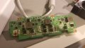
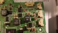
I'm looking at an LED driver board for an LED projector.

The projector I believe overheated and will not turn back on.

While looking at the LED driver board I noticed there are small solder pads all lined up together.

On some of the pads it looks like the solder moved away from the pad, and underneath there are a bunch of tiny through holes (obviously vias).

Anyways, is it possible that these pads when overheated allow the solder to move and open the circuit?

Just wondering if all I need to do is a quick reflow?
 

Attachments

dendad

Joined Feb 20, 2016
4,447
Yes, I have seen solder fuses. usually a length of solder between to tags on a strip in older valve equipment.
Also, sometimes a power resistor soldered underneath a couple of tags without the leads twisted through the tags. When the resistor gets hot enough, it melts the solder holding it on and drops off.

I don't think they will be fuses.
Could be extra mass for heat sinking, or setting options with a solder bridge.
Going by the amount of solder, if they were fuse, the board would be damaged before the solder would melt.
What is on the other side?
 

tindel

Joined Sep 16, 2012
936
I dont think thats a solder fuse. Hard to tell. It looks like the copper is gone and the exposed fr4 is showing.

It looks like there is a lot of black smoke around a couple of connectors. Have you got any shorts or opens on the connectors?
 

Thread Starter

electronice123

Joined Oct 10, 2008
339
The "smoke" is just marker to locate the connectors... but I see what your saying it does look like smoke.

Pic of opposite side attached.

Unfortunately the external power supply is good from what I can tell, that would have been easy.

Looking at those pads, there are multiple ones where it looks like the solder has flowed to hot spots, causing an open circuit.... Thats what I'm thinking anyways, I've just never seen pads like that before?
 

Attachments

dendad

Joined Feb 20, 2016
4,447
I think they are just to increase the current carrying capacity of the PCB. That is very common.
Have you been able to locate a service manual of the projector?
Also, have a look for a thermal fuse somewhere.
thermal fuse.jpg
 

Thread Starter

electronice123

Joined Oct 10, 2008
339
Yes I have the service manual.

I tested the external ps and it was putting out 19.5V so I know its good.

After that I tested each fan using a different ps, thinking if any were bad the sense line would prevent the circuits from turning on.

Next I followed the power through 2 connectors that power the LED driver board, all power and grounds were good.

So I believe its either the LED driver or the main board. I dont think I can troubleshoot the main board since its got a debug port, I'm assuming it requires special hardware/ software.

After doing more research I have found quite a few LG boards have been repaired by baking in the oven. Since its easier than reflowing with a soldering iron I'm going to try it. I'll let you guys know if it works in this case.... if not there are a few other things I will look at.
 

Tonyr1084

Joined Sep 24, 2015
7,829
Also, have a look for a thermal fuse somewhere.
While thermal fuses, commonly known as fusible links, respond to heat more so than current, soldering them onto a board is the quickest way to open them (blow them out). It's not likely you are going to see a fusible link on a circuit board. You more commonly see them in motors, particularly fans. If the motor bearings become dirty and the fan slows down then the motor over heats. The fusible link opens and shuts off the current so the motor doesn't start a fire.

What I see on your circuit board is nothing more than solder pads that may have some purpose for some upgraded (or downgraded) circuitry. They are most likely there to solder something with a metal body down to the board for structural strength while their leads are connected to the board elsewhere. Given the number of these pads I see in your second picture I'm thinking they're more for thermal mass than anything else. They're not carrying any current, and the ones in the first picture (didn't look that close at the second pic) are all common to one another. There is no electrical potential across them because they're all soldered to the same copper trace. So, no, these are not thermal fuses made from solder. Besides, a solder fuse would have to be very tightly controlled in its application. Too much solder and the "Fuse" can handle more current than the circuit can tolerate. Too little solder and the circuit will open prematurely. Fuses made from solder, though they have been used, are impractical (unless someone else here can enlighten me otherwise).
 

Thread Starter

electronice123

Joined Oct 10, 2008
339
Ok, so the solder reflow didn't fix the problem. Doing more troubleshooting I found the main board has a short somewhere in it.

This explains why every time I plugged it into the ps that it came with I would hear a spark then the ps would shut off.

Using my variable ps I set the votage to 1V, typically it runs on 19.5V @7 A.
At 1 V I realized the projector was pulling around 200mA and it wasn't even on! If I brought the voltage up to 3V it would pull over 1A so I quickly turned it off.

So, after disconnecting each connector until the only one left was the input power the short remained.

Now I'm stuck and don't know what to do. If I had an infrared camera I'm sure I could find the short easily... without one I'm not sure what to do?

The components on this board are so small I'm not sure how to even start troubleshooting it?
 

Attachments

Thread Starter

electronice123

Joined Oct 10, 2008
339
Ok, so i started taking readings across the capacitors C501,C510,C506 etc and noticed most of them are reading a short circuit (<1 ohm) when measuring directly across them one at a time.

So I'm thinking a surge destroyed the capacitors, and probably the entire board.

What do you guys think?
 

Attachments

dendad

Joined Feb 20, 2016
4,447
Is there a short across that cap?
If so, remove it and see if the short is fixed. It is probably only 1 cap.
Do you have the skill to work on a surface mount board?
 

Tonyr1084

Joined Sep 24, 2015
7,829
Checking capacitors in circuit with an ohm meter isn't going to tell you anything useful. You're reading far more from the other components than you might be from the component you're testing. You'd have to remove it to get an idea.

Cascading failures can be horrible to trace out. You find something that went bad and replace it only to learn that it destroyed something else. Now the work you just did is destroyed again because there were other faults.

You claim you have a short. Since I can't put palms on the PC (my hands on the board) I can only guess in general terms. If you can inject one volt then follow that volt until you completely lose it. Shorts are difficult to find. The closer you get to them the more difficult they become to find on a circuit board. With older PTH (Plated Through Hole) boards it was easy enough to desolder a leg and bend it out of the through hole and check for power, signal or ground. SMT (Surface Mount Technology) isn't so easy to troubleshoot. And fixing what you tested after you're done can easily lead to another short. And ZZZZzzzzzZzzzZZZZap! Back at square one.

Sometimes you stumble on the problem and solution. Most times you really have to know your stuff, which means having a schematic of the board. That way you could logically trace all the power lines and get closer to the problem. But then you have to desolder stuff in order to prove out whether there was a short.

Hey! Good luck.
 
Top