Facebook
 Google
 GitHub
 Linkedin
Hello newbie here. First time post hopefully in the correct spot. As most forums go yes I’ve searched but there’s just to
Much I don’t understand to be able to read the posts.
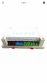
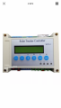
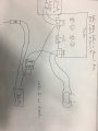
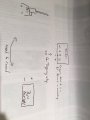
So my issue is I have a solar tracker for moving my panels. Trouble is the tracker only puts out 24vdc and the actuator to run it needs 36vdc at 3a. I have a power supply to provide the 36vdc but how do I wire relays to allow the actuator to receive the 36v when the tracker triggers movement. When tracker triggers it provides 24vs to actuator. I’ve have hooked 1-(5pin) with sucess. But when I add a second only 1 still works. I’ve attached a pretty drawing
I need basic configuring as my electronics knowledge isn’t great.
Thank you
Much I don’t understand to be able to read the posts.
So my issue is I have a solar tracker for moving my panels. Trouble is the tracker only puts out 24vdc and the actuator to run it needs 36vdc at 3a. I have a power supply to provide the 36vdc but how do I wire relays to allow the actuator to receive the 36v when the tracker triggers movement. When tracker triggers it provides 24vs to actuator. I’ve have hooked 1-(5pin) with sucess. But when I add a second only 1 still works. I’ve attached a pretty drawing
I need basic configuring as my electronics knowledge isn’t great.
Thank you
Attachments
-
 89.6 KB Views: 21