Facebook
 Google
 GitHub
 Linkedin
Hi all
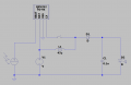
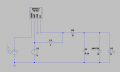
I have an RGB LED led that needs more or less 3 volts to perform correctly its light routine.
Can I use for my project a 3.3V zener diode?
Only using the rectifier diode and the cap as a buffer the voltage would be a rather constant 4.8V.
Cheers
I have an RGB LED led that needs more or less 3 volts to perform correctly its light routine.
Can I use for my project a 3.3V zener diode?
Only using the rectifier diode and the cap as a buffer the voltage would be a rather constant 4.8V.
Cheers
Attachments
-
 17.3 KB Views: 19