Solar Panel 9V battery iPhone charger

Status
Not open for further replies.

Thread Starter

Shrinee

Joined Aug 16, 2014
2
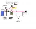
Hello, I am trying to make an iPhone charger. I have a 9v solar panel
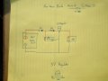
To charge a 9v rechargeable battery then to charge my phone but I can't seem to find the problem that I am making. I have diodes between the solar panel and battery and the battery and the 5v regulator on positive lead. Help me where I went wrong!
 

Attachments

shteii01

Joined Feb 19, 2010
4,644
Sorry should have mentioned this in first post. When I plug my iPhone cord in nothing happens.
Hm. There are some phones that require some additional pins to be activated in order for the phone to accept the charge. You might want to look into which pins of the plug that goes into the phone need to be used for the charging.
 

wayneh

Joined Sep 9, 2010
18,098
You could eliminate the second diode.

iOS devices generally do require the data pins to see proper voltages. Also, inadequate current will prevent charging. A typical 9V battery cannot likely provide enough current.
 

djsfantasi

Joined Apr 11, 2010
9,237
As WayneH pointed out, the data pins need to see some voltage to enable charging an iPhone. The circuit below illustrates using resistors in a voltage divider arrangement, to provide the proper voltages for an iPhone.


shteii01

Joined Feb 19, 2010
4,644
As WayneH pointed out, the data pins need to see some voltage to enable charging an iPhone. The circuit below illustrates using resistors in a voltage divider arrangement, to provide the proper voltages for an iPhone.

Am I understanding correctly that USB end is the one that goes into the iPhone?
 

IcedFruits

Joined Jan 15, 2014
100
dont put voltage regulator there that way, if no battery is there. solar panels dont stick to a constant voltage when current is drawn. soon the panel voltage will reach a level below regulator minimum headroom, and it will shut down the regulator o/p i think ?

and 9v panel - diode < 9v battery.
 

wayneh

Joined Sep 9, 2010
18,098
The output voltage of the regulator will sag if the source voltage sags, it doesn't really "shut down". But the regulator can be damaged if a voltage is applied to its output - by a battery or a capacitor - that exceeds its input voltage. Many schematics show a reverse biased diode across the regulator for this purpose - it routes the reverse current around the regulator instead of thru it.

I don't believe an iPhone would put power on its USB power pins, so I don't think this is a problem for this application. Worth checking, I guess.
 

Brian325

Joined Oct 3, 2015
9
hello guys im new to the forum i am working on a similar project to the one mentioned above. i have drawn up a very simple schematic i haven't wired anything yet. if someone could check it for me just to make sure i have no problems thanks Brian

i am using
a car charger usb with 34063ap1 chip.. so the voltage will be relegated correctly (i think)?

9V 3W Mini Solar Panel
led indicator
2 1N914 Schottky Diode

9V Volt 300mAh Ni-MH Rechargeable Recharge Battery
2 switches
voltage meter

i will attach schematic below


Attachments

Brian325

Joined Oct 3, 2015
9
I do not think that there is such a thing as a 1N914 Schottky diode.
i got my specs from a website that sells kits my design is just a little modified there is a 1N914 Schottky diode but not sure what the difference is from a Zener Diode or even if there is a difference

here's a link to a Schottky diode

http://www.ebay.ie/itm/121170158654?_trksid=p2060353.m1438.l2649&ssPageName=STRK:MEBIDX:IT


if you have any recommendations for my attempt at this project id be glad to hear them thanks

kind regards Brian


ISB123

Joined May 21, 2014
1,236
2$ for a schottky diode!!!!!!!It must be made of gold.....

Draw a clearer schematic yous is hard to interpret.
 

Brian325

Joined Oct 3, 2015
9
2$ for a schottky diode!!!!!!!It must be made of gold.....

Draw a clearer schematic yous is hard to interpret.
thanks for the advice i will draw up a new one and post it ASAP hopefully it will look better and easier to read

im not really sure what is made of maybe gold as it is a good conductor of electricity thats what the kit said to use 1N914 Schottky diode im sticking to it as best i can to avoid unnecessary errors as i have no experience with electrical components this is my first time
here is a look at the new schematic i left out the leds for convenience.Device Schematic new draft.png
 

wayneh

Joined Sep 9, 2010
18,098
You have another thread running on this. You should keep your posts over there instead of bringing this old thread back to life.
 

WBahn

Joined Mar 31, 2012
32,783
hello guys im new to the forum i am working on a similar project to the one mentioned above.
So start your own thread instead of necrohijacking someone else's.

Wayneh mentions that you already have another thread of your own. So use that. If there is something in this (or another) thread that is relevant, post a link in your thread.
 
Status
Not open for further replies.
Top